
Hunter Sawyer Assembly
We know you are a true craftsman and assembling this masterpiece is just the challenge you don’t shy away from.

This assembly video is for the Hunter/Sawyer portable sawmill. There is no welding required for this assembly. You only need a handful of shop tools (see list below). This sawmill can out-perform the competition in its price and class. Designed to keep you ahead of wood milling challenges no matter the project. We built it tough!
See Complete Written Instructions Below
Looking for the Original Hunter/Sawyer Directions
(April 2023 and older) Click Here
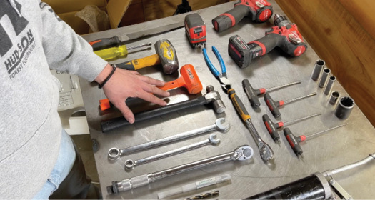
Here is the list of tools that you will need for assembly:
WRENCHES
2 – 9/16”
2 – 3/4”
7/16”
5/8”
1/2”
Allen Wrenches
3/16”
5/32”
Sockets
3/4”
1 3/8”
1 1/8”
9/16”
5/16”
1/2”
13mm
10mm
8mm
Drill Bits
1/4”
1/8”
Impact Gun
Vise Grips
Cutting Dikes
Torque Wrench
Hammer
Rubber Mallet
Ratchet Handle
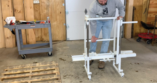
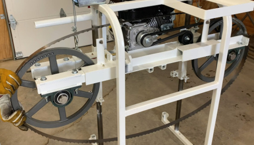
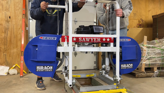
Unpacking your mill (Video-0:10)
Work area should be clean and as level as possible for ease of assembly.
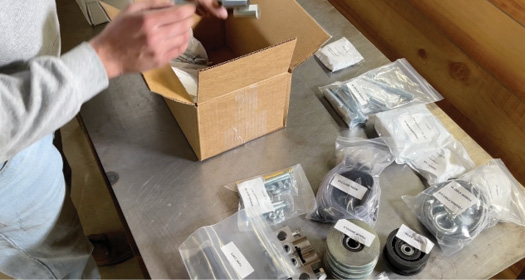

Remove and separate all like parts.

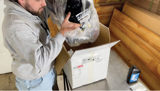
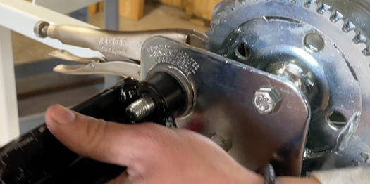
Engine Preparation (Video-3:08)
Remove engine from the packaging.

Remove crankshaft bolt and discard.
Remove and discard the keystock that is provided with the engine.

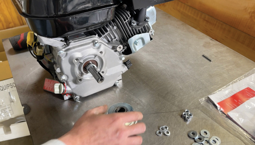
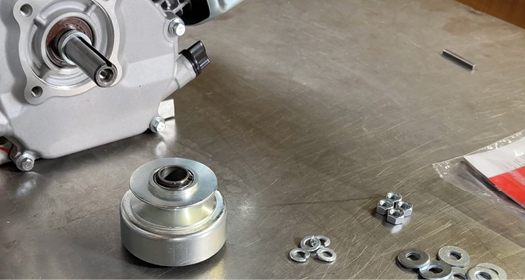
Install two spacer washers (PKG 14) on the crankshaft.

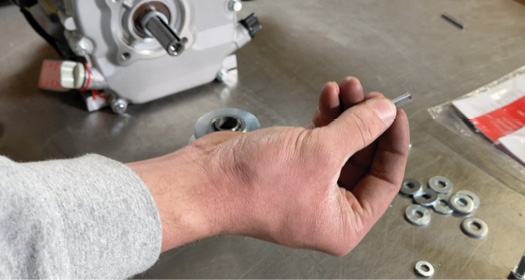
Use the shorter key stock that is provided by Hud-Son and install on the crankshaft.

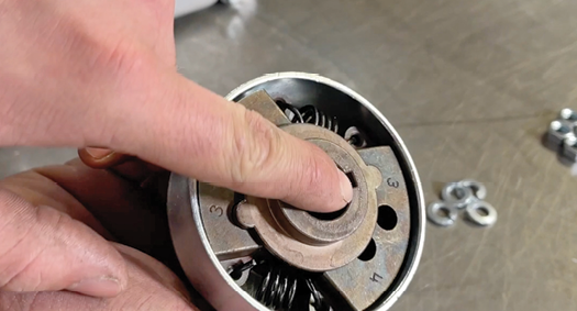
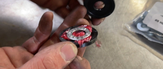
Install the clutch with the guide facing the keystock.

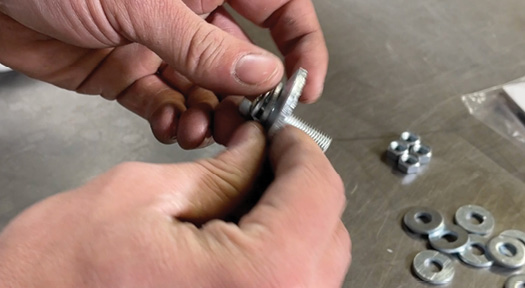
Assemble the Clutch Bolt: put the lock washer, flat washer, and serrated washer on the clutch bolt (PKG 14).

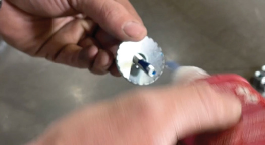
Put Loctite on the threads at the end of the bolt. Thread into crankshaft.

*install as shown*
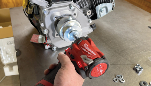
Tighten the bolt to install the clutch with an impact wrench with a 12mm socket.

Remove dipstick and add engine oil as recommended by the engine manufacturer. Check dipstick to show that oil is full.

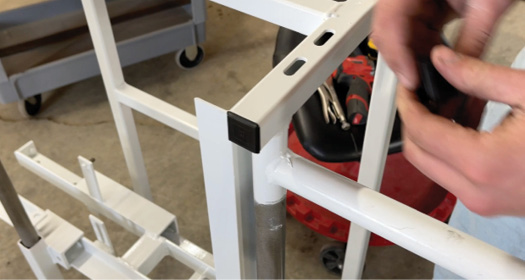
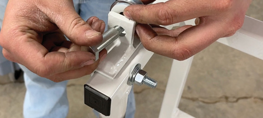
Install Caps (Video-5:38)
Install caps into open ends of the frame.

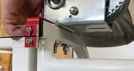
Install Sightglass (Video-5:43)
Place sightglass on red bracket and tighten up (not too tight so as not to crack the glass). Make sure glass lines up with side and bottom of bracket. 
Install on frame. Leave small space between bracket and frame. 
Secure with self tapping screws.

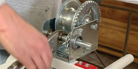
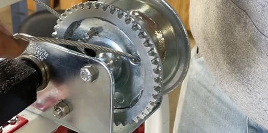
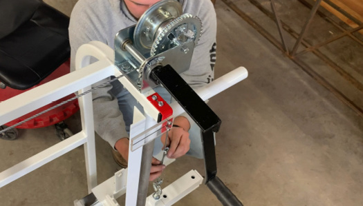
Installing The Winch Assembly (PKG 3) (Video-7:02)
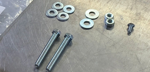
Grab 2 flat washers, a lock washer, and nut for each bolt.

Install winch on winch bracket with the two bolts provided and tighten bolts.

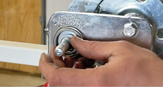
Install wooly washer on end where handle will attach.

Put a vice grip on the winch.

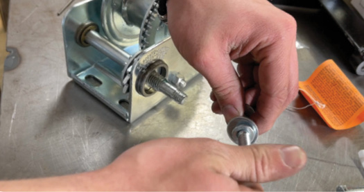
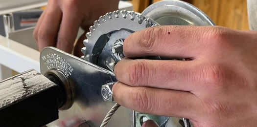
Install the winch handle by threading the handle onto the winch. Locate the winch handle hardware: the bolt, washer, spacer and spring.

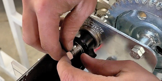
After you thread the handle, add a spring then a nut.

Tighten the handle and then with a pair of pliers, clamp the winch shaft while rotating the handle and then tighten the bolt on the handle.

Installing The Cable Guide Assembly (Video-9:04)
Install bracket on to frame using the 2 bolts provided. There should be a flat washer on either side of the frame. Add spacer washer and nut to finish and tighten.

*You will have a shoulder bolt, two nylon spacers, washers with the cable guide*
Install a nylon washer on each side of the cable pulley, insert into bracket. Finish with a flat washer and a ny-lock nut to hold the assembly in place.

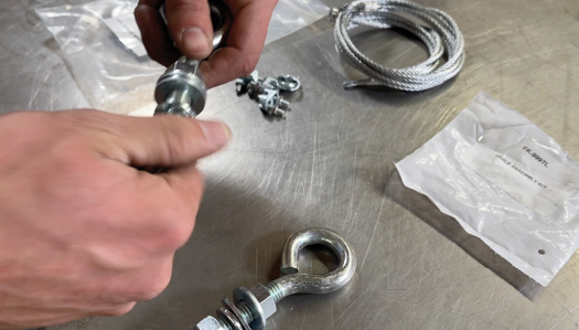
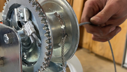
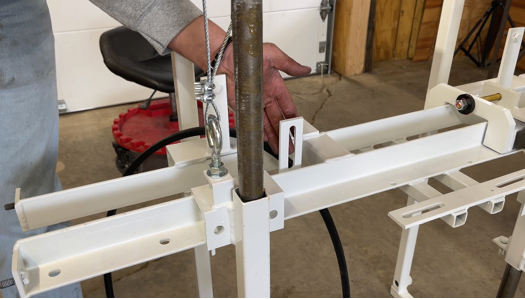
Installing Winch Cables (PKG 10) (Video-10:00)
Assemble the eye bolts. Thread the nut on to about a half inch from the top. Add flat washers, lock washers and nut.

Leave one flat washer on and place eye bolt through the frame. Add additional washers and nut and secure. Repeat on opposite side.

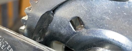

Dent the cable winch with a chisel and hammer to install the hardware, otherwise the cable will not fit properly and lay flat. The square should be open when you’re finished.

Drill hole to slip cable through.


Slip long cable through backside hole, place the loop on the screw.

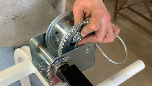
Clamp and tighten.

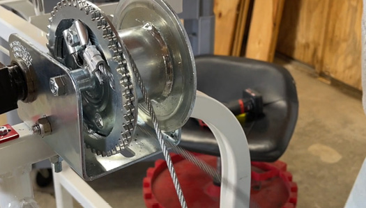
Wrap all the way around winch once from underneath, then across to the cable pulley.

The longer cable goes under the bale across the mill over the cable guide and down to the discharge side.

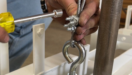
Run both cables through eye bolts, install 2 cable clamps facing away from the mill, as far down and as tight as you can to the eye bolt.

*Shorter cable will go straight down to the operator side*
Feed shorter cable through the hole you drilled. Loop once around winch from the bottom and down to eyebolts.

Install both cable clamps and tighten.

After winch and cables are installed, check head for binding. Lubricate the mill just enough so the mill head can move smoothly.

Lift head up (lubricate lower part of the mill) and then back down. If head is binding, cables must be adjusted evenly.

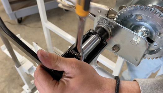
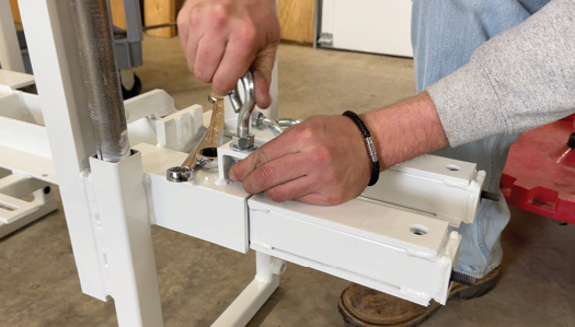
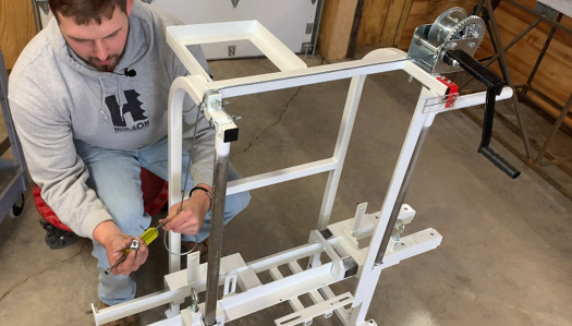
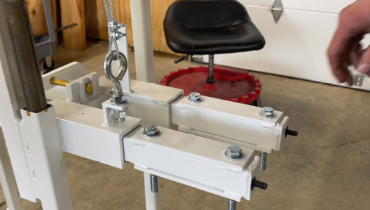
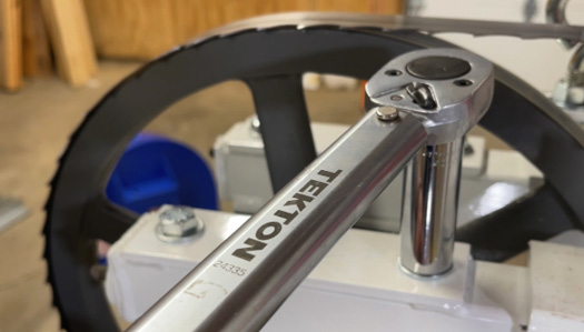
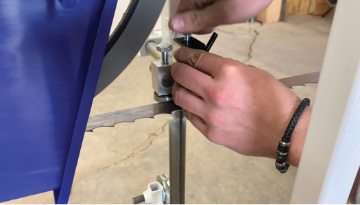
Installing The Tension Bolt (PKG 8) (Video-16:12)
Grease cup washers, making sure the lip side is up, install thrust bearing in center, then add second cup washer, lip side facing the first washer.

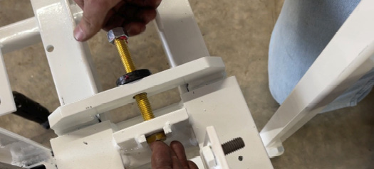
Put the bolt through the frame then add a cup washer then the nut. Secure.

Installing Bearing Stop Bolts (PKG 8) (Video-17:12)
Thread nut onto bolt, leaving a half inch. Install 2 flat washers and additional nut. Install on the drive side. (One flat washer and nut on either side of the frame.)

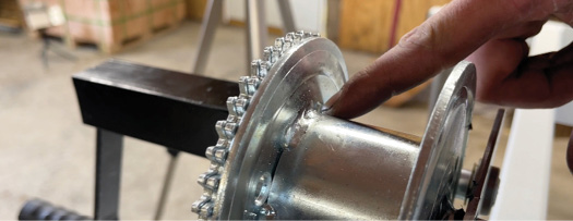
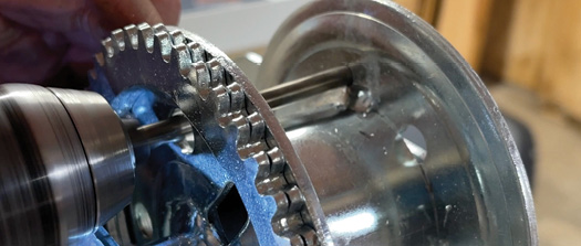
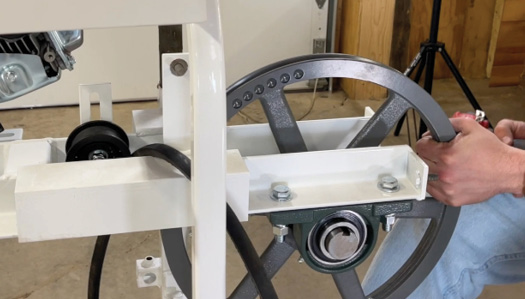
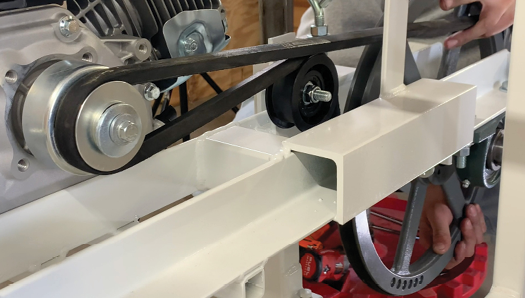
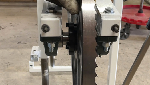
Installing the Band Wheels and Shaft (PKG 7) (Video-18:15)
First take the drive belt and put it on the drive side wheel, this will enable you to install the belt later.

Locate the wheelshaft and bearings. Use the half inch bolt and two half-inch washers one thick and one thin, a half-inch lock washer and a half-inch nut. The long bolts will go on the thicker side.


The shorter bolts go on the thin side (with the drive belt.)
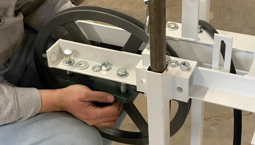
The wheel that doesn’t have the band on the wheel goes on the thinner side with the drive belt. Hold the wheel up with your knees, the hub facing the operator side of the mill.
 Put the thin washer on the top under the head of the bolt. The bolts will go through the frame into the bearing, then the thick washer, the lock washer and the nut.
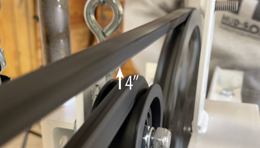
Repeat the process on the other side. Snug all eight bolts. *Measurement from wheel to mill head on engine side should be 1 inch.*

Band Wheel Vertical Alignment (Video-20:58)
*The mill head will have to be on a level surface.*
Use a level to check and see if the mill head is vertically aligned correctly.
![]()
If not, you may need to add a bearing shim. Check both sides for alignment.

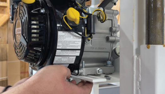
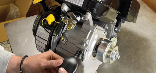
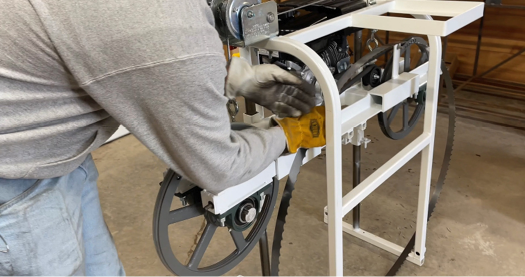
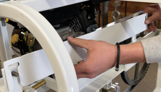
Installing the Engine (PKG 6) (Video-21:59)
Use the four 5/16 bolts provided with flat washers under the head of the bolt and finish with a flat washer, lock washer and nut on the bottom. Push engine against mill head as tight as possible. Tighten bolts.

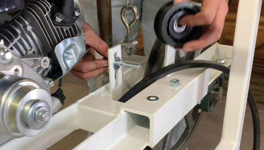
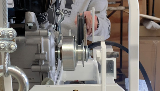
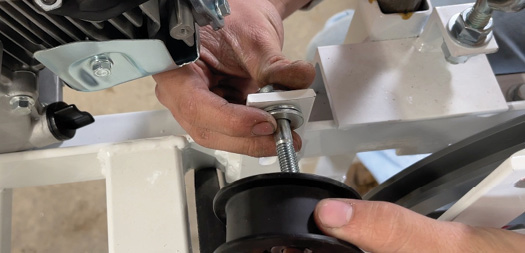
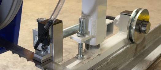
Installing the Idler Wheel Assembly (PKG 9) (Video-23:22)
(Tension Pulley) Use the shoulder bolt with a larger USS 3/8 flat washer on the head of the bolt. Insert it through the frame and add the other USS large flat washer.

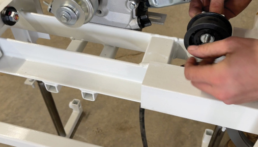
Add idler pulley, and SAE small flat washer and nut.
*Do not tighten the idler wheel assembly yet.*

Pull Band Wheels out all the way and tighten up bolts. Repeat on other side.

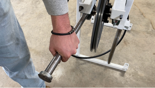
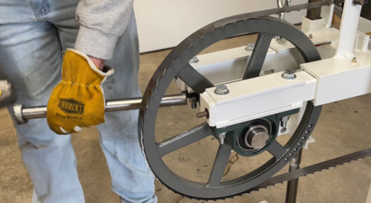
With a hammer and rod, move the wheel closer to the engine side by tapping on the backside of the bearings.


Loosen up set screws on the inside to easier align build with clutch. Use a mallet to tap the bearing. Once aligned, tighten set screws.

Install drive belt around clutch and over idler pulley.
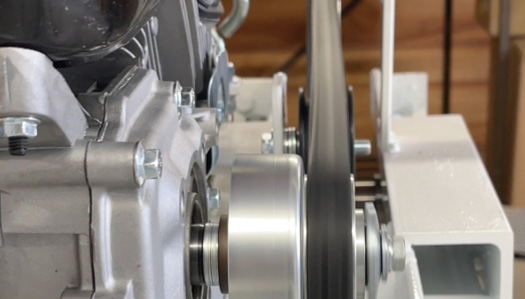
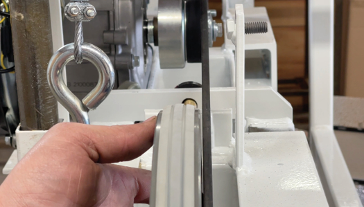
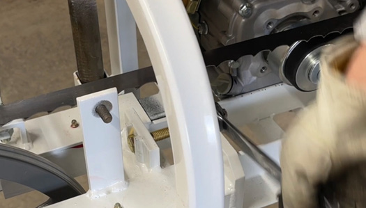
Take belt about two thirds around band wheel leaving the top one third off.

Belt should sit in the middle of the pulley. Here it is not.
![]()
When not centered, take off the belt, remove the pulley and add an extra washer, then reinstall pulley. 
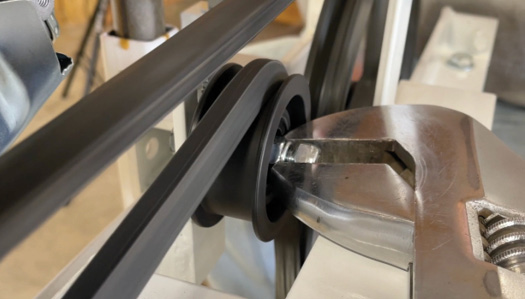
Twist bracket by adding second nut and use wrench to pull and twist the pulley to get the belt to run in the center. If it doesn’t, repeat process of adding additional washer. Belt MUST run in the center, otherwise it could flip and the blade can come off with the engine running.

Once adjusted, roll belt on by turning band wheel.
Once on deflection should be no more than a half inch with 5 pounds.

Add gas to engine.
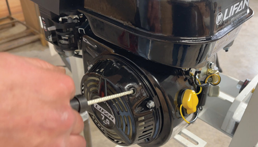


Start engine (make sure its in on position, choke before starting, then pul handle to start), run and check belt for alignment. If belt flips on wheel, adjustments need to be made by shimming the wheel.

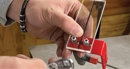
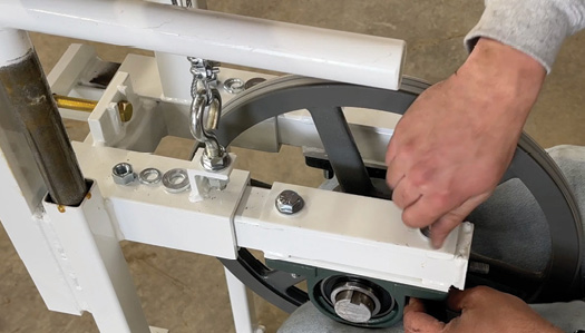
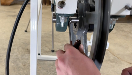
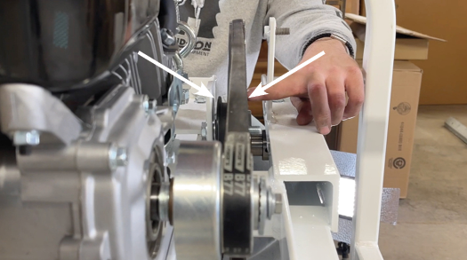
Drive Wheel to Clutch Alignment (Video-30:00)
Place straight edge on face of band wheel and align with clutch. Use hammer and rod to tap on the bearings to align. *about 3/16 gap between right edge and side of clutch pulley

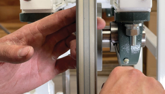
Loosen up set screws on the inside to easier align build with clutch. Use a mallet to tap the bearing. Once aligned, tighten set screws.

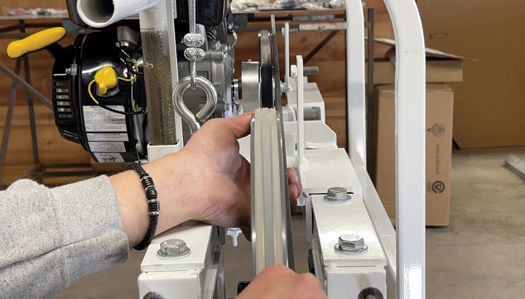
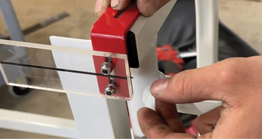
Band Wheel Alignment
Once drive wheel is aligned with clutch (just barely touching the clutch) you will have aligned operators side wheel with drive side wheel.

Both wheels should be flush all the way across on straight edge.

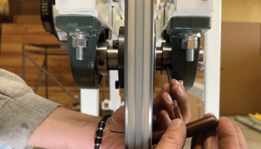
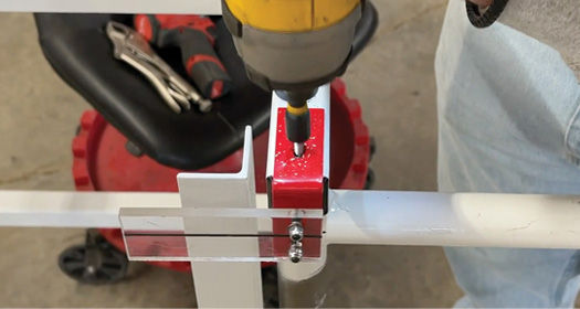
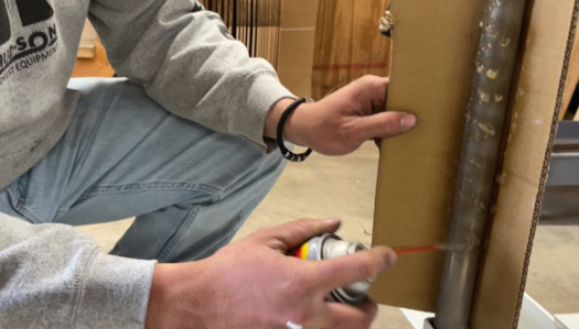
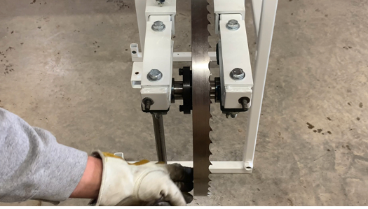
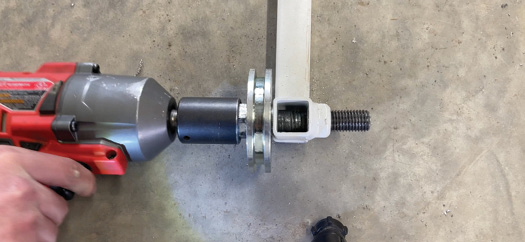
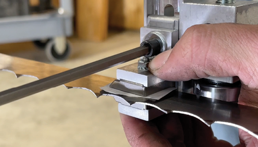
Drilling and Set the Shaft (Video-31:57)
Remove one set of screws from pillow block bearing using a 5/32 allen wrench.

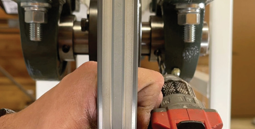
Using a 1/4 drill bit drill 3/32 in shaft, clean threads with carburetor cleaner or compressed air.
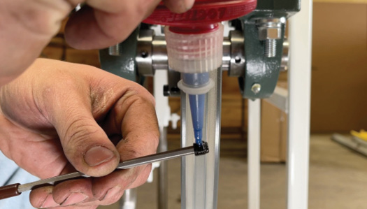
 Apply locktite to set screw. Reinstall. This will be done on all four bearings. Drilling and setting will hold shaft from moving in the bearings.

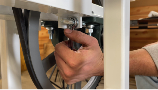
Install Zerk fittings into frame in pre-drilled holes at the tensioning system. Use needle nose pliers to hold Zerk fitting and tap with a hammer.

Grease the tensioning system. Slide back and forth to apply grease.

When you install bolts for bearings, make sure all bearings are torqued to 85 foot pounds.

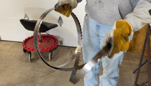
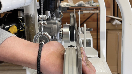
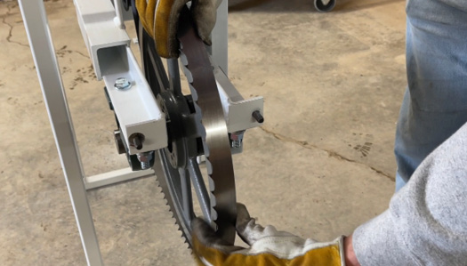
Installing Band Blade (Video-33:56)
Unfold band blade as shown using gloves.

Slide blade between frame and band wheels.

Loosely place blade on band wheels, make sure teeth are facing toward discharge side.

Make sure blade sits flush to back of wheel.

Snug blade with tensioning bolt, do not set tension yet. Turn the blade in directional rotation (toward discharge side).

The blade is no longer flush with the back of the band wheel, so adjustments need to be made.

For blade alignment use large punch or steel bar with hammer to tap the bearings in toward the engine to align the blade. If the blade is running off the backside of the wheel, you can align by tapping the front bearing. If the blade is running off the front side of the wheel you must tap the back bearing.

Turn the wheel a few times to make sure the blade stays flush.

Once blade is aligned, tighten all bolts in pillow block bearings.

Tension blade to 35 foot pounds. Recheck blade alignment when done.

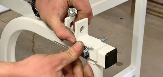
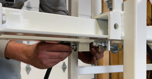
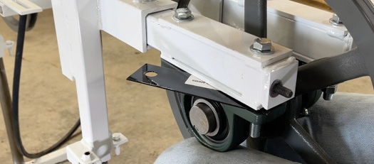
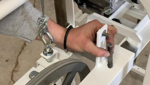
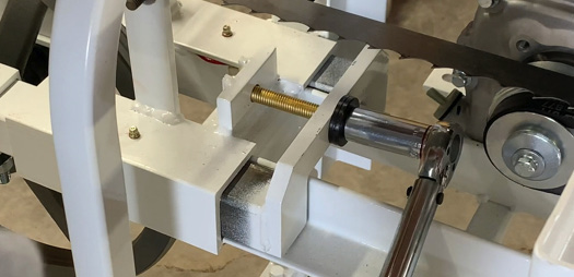
Installing the Off Deck Bolts (PKG 8) (Video-37:38)
Use the 3/8” by 3 inches long tap bolts, adding a nut after you’ve threaded it through the frame.

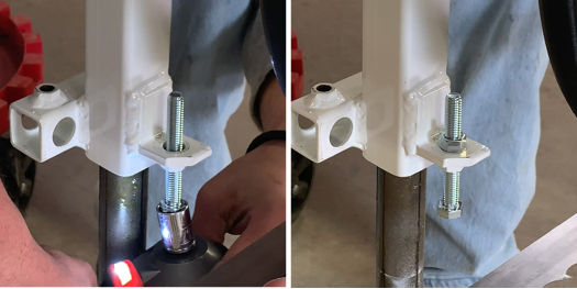
Install on each side. Off-deck adjustment is done later once the mill head is on the track.
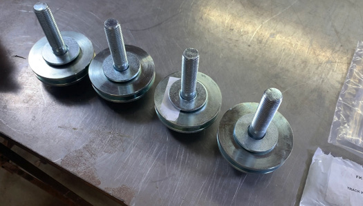

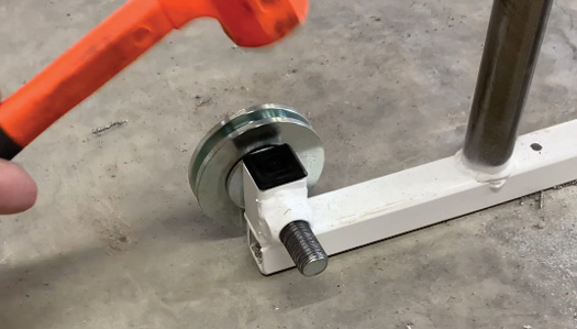
Installing the Track Wheels (PKG 5) (Video-38:45)
Use the large shoulder bolts, two spacer washers and a large washer. Small washers go on after the wheel then the large flat washer will be against the frame.

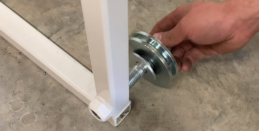
The wheels will be on the inside of the mill frame. Grease bolt before inserting.

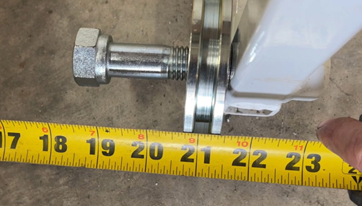
Measure wheels from outside of left track wheel to inside of right track wheel so they are 20 and 3/4” apart. If it does not measure to this, add or remove washers between wheel and frame to achieve proper measurement.

Do all 4 wheels. Check to ensure the wheels spin freely.
This will complete the inner head assembly.

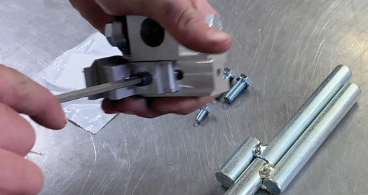
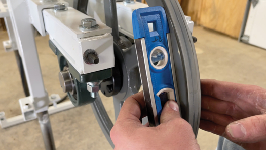
Blade Guide Installation (Video-41:39)
Prep the guides by loosening the allen bolt in the center of the guides.

Insert guide pin into the frame with offset facing towards outside of the mill frame.

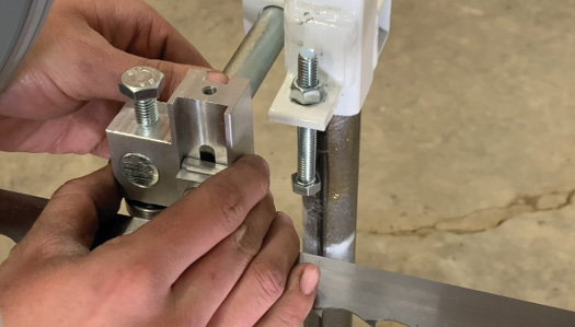
Place guide over the blade move the guide pin into position, and slide guide onto Pin, flush with the front of the guide pin.

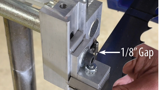
There should be a 1/8” gap between your blade and the bearings on the guide.

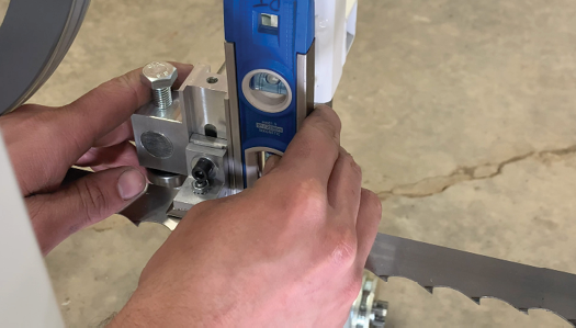
Make sure your guide is level with the frame before tightening. *Repeat on the other side.*

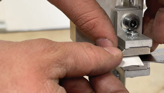
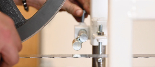
Aligning the Blade Guide (Video-45:39)
*The blade should be in the center of the backstop bearing.* Take a piece of paper, fold in half and place it over and under the blade.

Hold guide shoes to the paper and tighten the allen bolt. The blade will now be adjusted and set. *There will be an 1/8” space between the backstop bearing and the back of the blade. Make sure all bolts are tight when done.*

Installing the Guards (PKG 11) (Video-46:25)
Use a 3/8” flat nylon washer to install center blade guard and backing white.

Place the guard, the washer, lockwasher then the nut to hold to the blade guard in place. Tighten

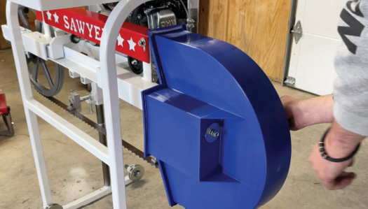
To install the end guards, place nylon washers, slide the guard onto the bolts located at the sides of the mill. Use the large flat washers, lock washers and 3/8” nut to hold in place. Line up with center guard. Tighten bolts.

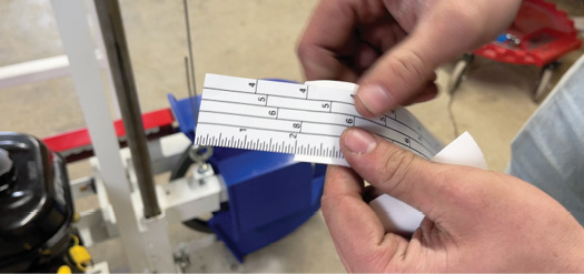
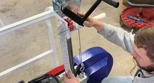
Installing the Scale Sticker (PKG 13) (Video-48:53)
Rip off the top 2” of backing tape.
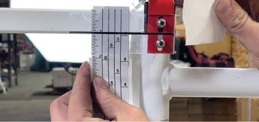

Installing the Scale Indicator (PKG 12)
Place on the frame. It will be installed at the 1” mark on the scale. Peel backing as you secure sticker to frame all the way down, pulling taut.


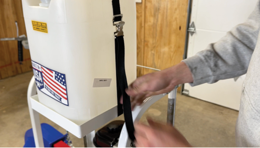
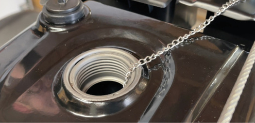
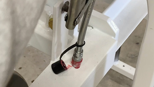
Installing the Lube Tank (Video-49:23)
*The lube tank has a bracket that is welded to the top of the mill for the tank to sit in. Install the lashing strap through handle and under the bracket. Cut to length.

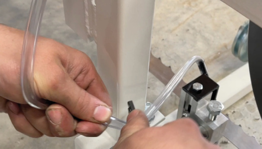
Installing the Lube Line (Video-49:58)
Install lube line bracket on top of the blade guide. Lower sawmill all the way.

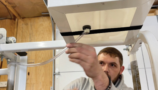
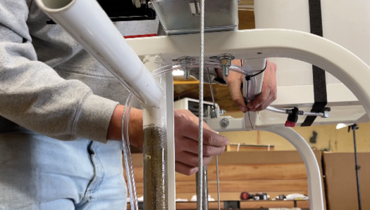
Start lube line from the fitting at the bottom of the tank.

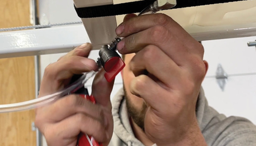
Cut the lube line to install the shut off valve. Use the arrows on the valve to place correctly. Follow the flow – will always be down.

Zip tie in place. Zip tie lube line across the top of the mill frame and down the side , alongside scale sticker.

Cut the line again to add another barbed fitting. This will allow you to take the line apart to change the blade.
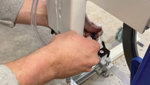
 Attach to the black lube bracket on the guide.

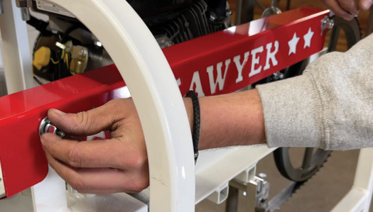
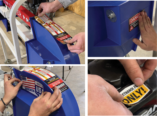
Add stickers (Video-52:20)
Grab the provided sticker sheet and attach stickers as shown.

* Start sawmill from lowest position to ensure it runs properly.
ALWAYS LOOSEN YOUR BLADE WHEN YOU’RE DONE USING IT.
.jpg)
Install additional caps (Video-53:30)

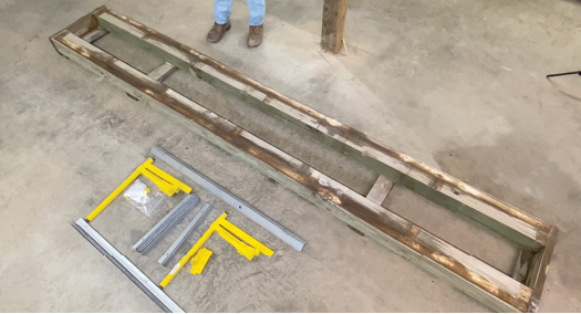
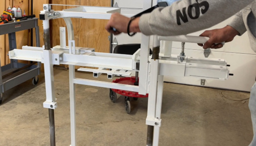
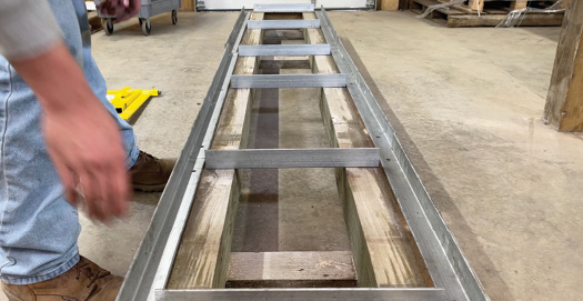
Putting the Track Together (Video-53:43)
*If you are using the standard steel track you will need a support base. In the instructional video, we are using 6” x 6” timbers. Timbers or lag bolts are not included with your sawmill*
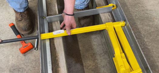
Start by setting your track support base up, making sure it is square.

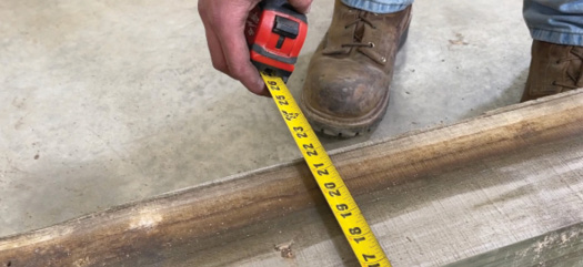
Support base should measure 21 3/4” wide.

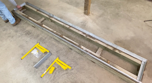
Place all of the steel side rails on your support base.
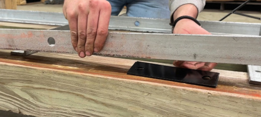
Rails are labeled. Make sure end cross members have the 3/8 hole pointing down and wider holes facing out.

Place middle cross members according to the bolt holes.

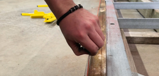
Use a chalk line to ensure rails are lined up and a 1/2” from the outside edge of your base.

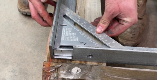
Line side rails up to chalk line and square up side rails with end cross member.
![]()
Make sure you are working on a level surface. Shim side rails if necessary.

There are three 3/8 holes in the side rails (they should be facing down). The 3/8 holes are for lagging the track to your support base. There will be a 3/8” hole on the side. This is use for the attaching the log dogs. Make sure middle cross members are flush and square to the side rails before securing to the base.

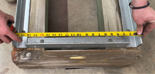
Double check the rails are 20 3/4” apart.

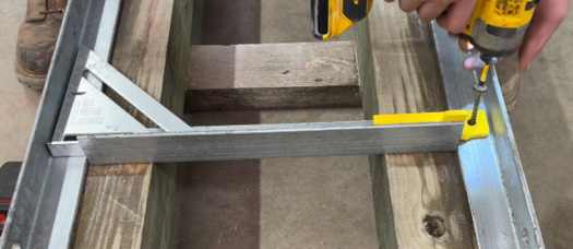
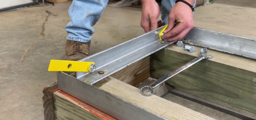
Place crossmembers 24” apart between siderails making sure cant stops are on the discharge side of the track. “Cant stops are the yellow tabs that bolt the crossmembers to the side rails.”
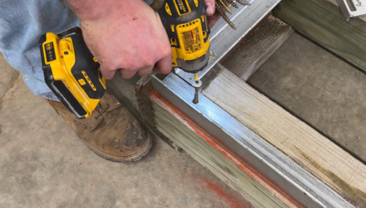
Once the track is laid out on the 6” x 6” support base, make sure everything is square. Once the track is square, mount the track to the 6” x 6” support base using lag bolts. *Lag bolts are not included.*

Install all four end stops. This keeps the mill from running off the end of the track. (PKG 15)

Installing Log Dog Assembly (Video-1:01:24)
Backstop should be on the same side as the cantstops (B side of the mill; the dog will be on the A side of the mill.)
Remove axle. Place log dog in track and slide axle through track, log dog and through the track on the other side.Tighten set bolt.

Put the mill on the track (Video-1:02:17)
Turn end stops in. Use 2 people to lift mill onto the track. Flip end stops back out.

Off Deck Setting (Video-1:02:34)
Tighten blade. Thread off-deck bolts into frame to achieve a 1”off-deck setting on each side of the machine. Make sure blade is tight.
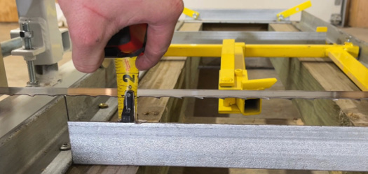

Measure from the bottom of the blade to the top of the cross member.
*This should measure 1” on each side. If this measurement is off, the off deck setting bolts can be
adjusted to achieve the 1”*

Raise the head and start sawmill again to ensure it runs properly down the track.
ALWAYS LOOSEN YOUR BLADE WHEN YOU’RE DONE USING IT.
CORRECTIONS FOR IMPROPER ASSEMBLY OF MEASUREMENTS
1. CAGE MEASUREMENTS
– Use the extra washer in the cage assembly hardware kit to correct any offset measurement.
– If needed, the shim washers will be installed in the inside of the center cross beam.
– Recheck that the measurement is equal on top and bottom of the lift tubes, tension bolt.
– Hardware fits together so there is a small space instead of the wrong way which is a bigger space.
– Use a level to check in see if the mill head is vertically aligned correctly. If it is not, you may have to install shims between the bearing and the mill head. The manufacturing process during welding may cause differences to the inner head frame red shims.
2. TRACK WHEEL ALIGNMENT
-If it does not measure 20 3/4 apart, adjust number of alignment washers accordingly to achieve this
measurement.