We know you are a true craftsman and assembling this masterpiece is just the challenge you don’t shy away from.

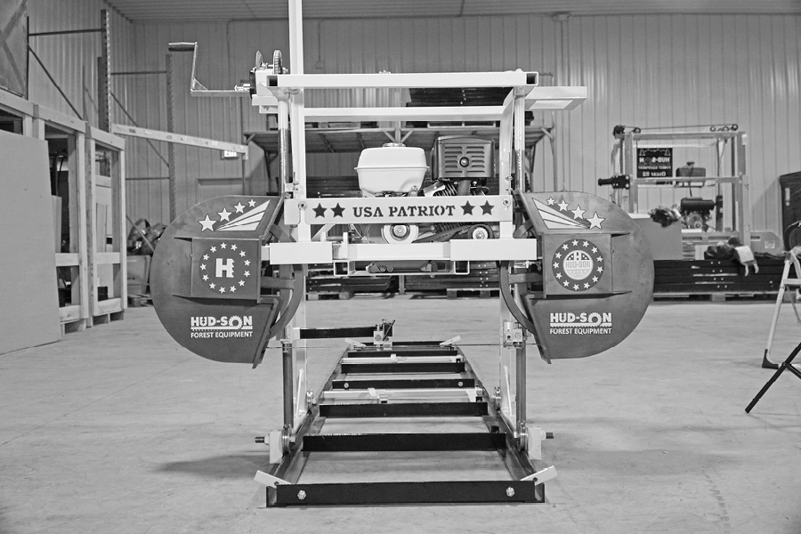
This assembly video is for the Patriot portable sawmill. There is no welding required for this assembly. You only need a handful of shop tools (see list below). This sawmill can out-perform the competition in its price and class. Designed to keep you ahead of wood milling challenges no matter the project. We built it tough!
See Complete Written Instructions Below
Assembly Instructions for the Patriot Sawmill
(Instruction video times are posted with each step)
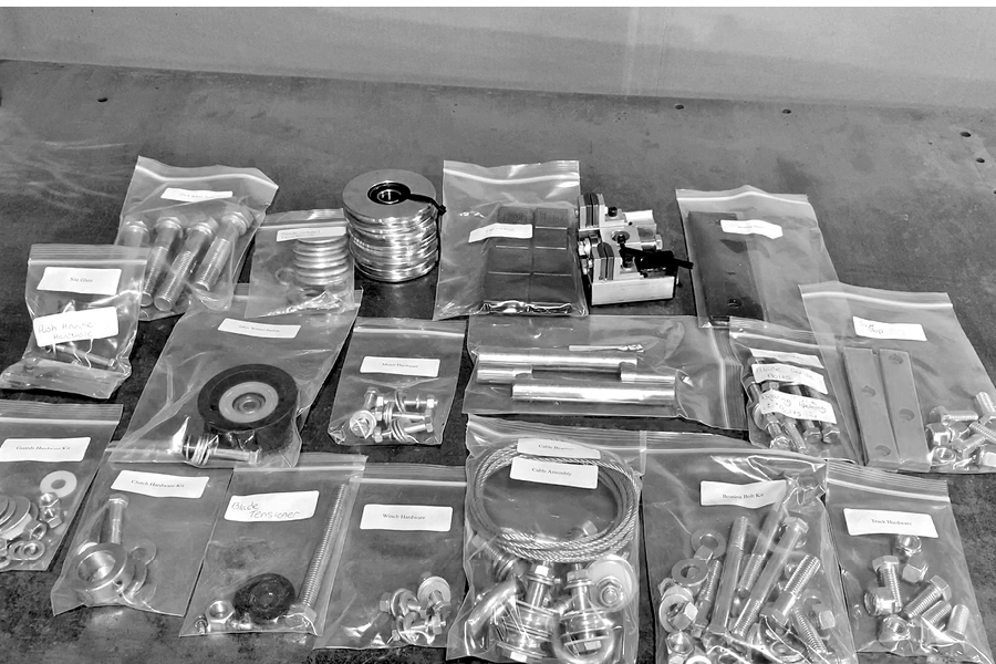
1. It is best to have a large area where you can unpack your mill and lay out your parts so they can be seen plainly.
2. Remove the sides and ends of the crate with a hammer and unpack the boxes and lay them out.
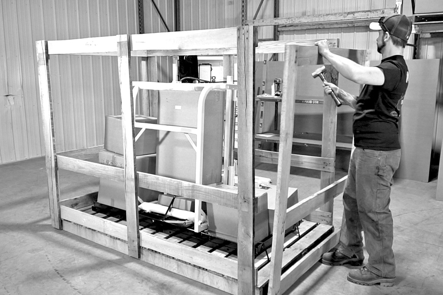
3. Cut the straps that are holding the mill head to the pallet and then slide the head off of the pallet onto the floor.
4. Set the track sections to the side and move the pallet out of your way.
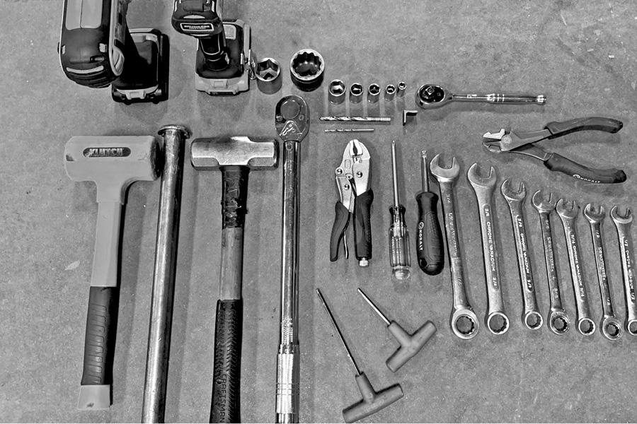
5. Here is the list of tools that you will need for assembly:
WRENCHES
2 – 9/16”
2 – 3/4”
7/16”
5/8”
1/2”
Allen Wrenches
3/16”
5/32”
Sockets
3/4”
1 3/8”
1 1/8”
9/16”
5/16”
1/2”
13mm
10mm
8mm
Drill Bits
1/4”
1/8”
Impact Gun
Vise Grips
Cutting Dikes
Torque Wrench
Hammer
Rubber Mallet
Magnetic Bolt Tray
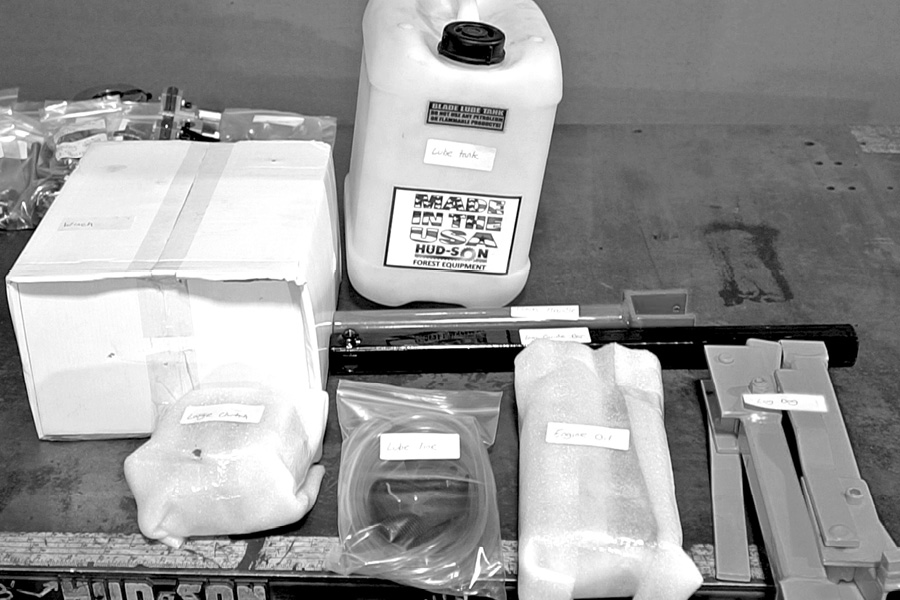
6. Open all your parts boxes one by one and lay out the parts so they can be clearly seen. All the bags are marked clearly with the parts inside. Keep the hardware in the marked bags until it’s time to use it.
7. With all your boxes open and your parts laid out, you’re now ready to start assembly.
Step 1 (Video – 1:43)
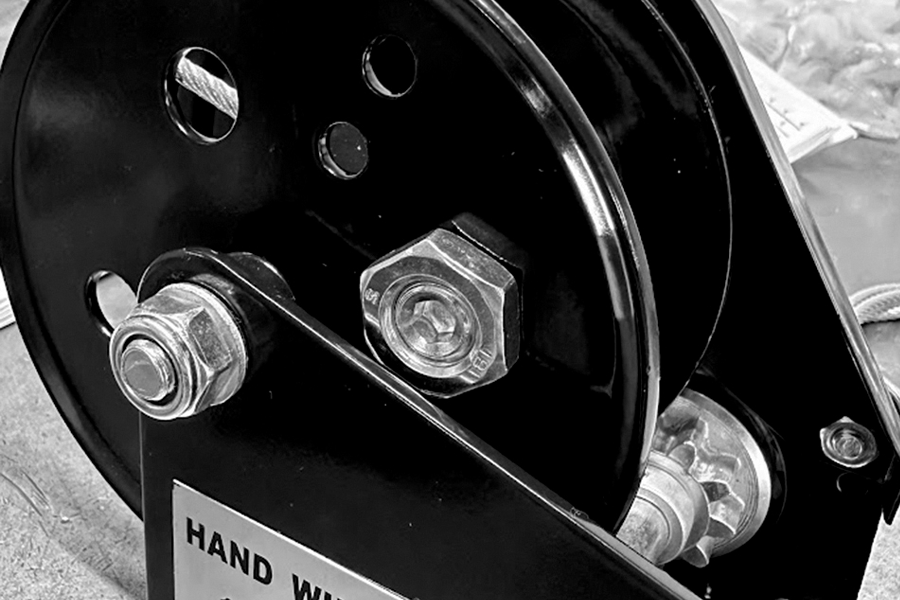
Installing the winch on the frame
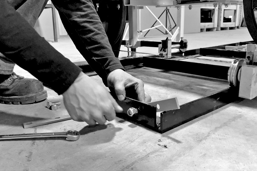
A. Install the winch on the frame, keeping it square to the mounting plate, slide toward the operator using the supplied hardware kit, tighten nuts and bolts securely.
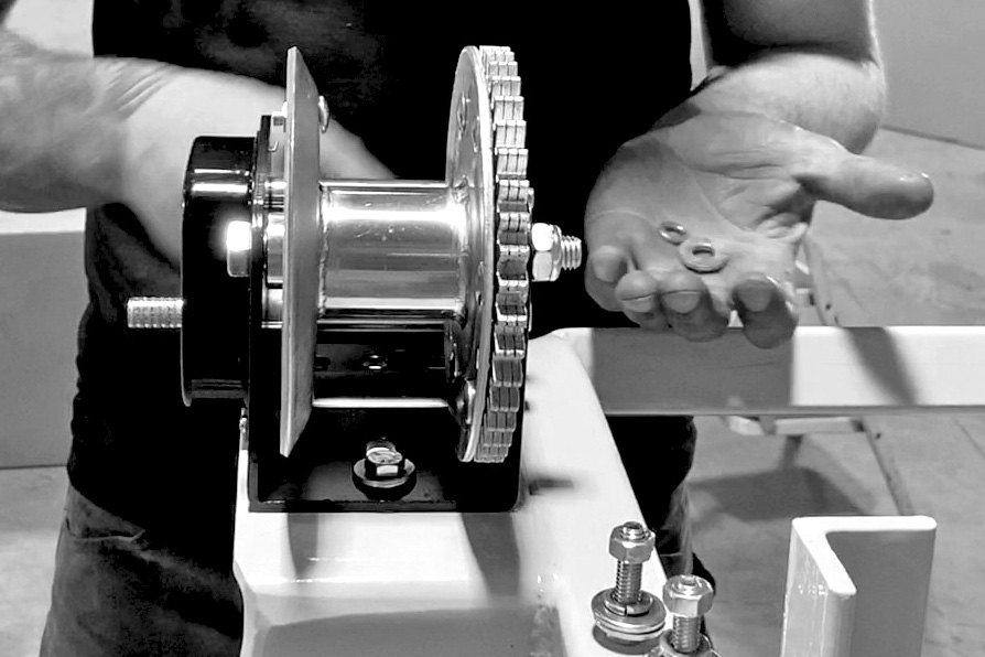
B. Install the winch crank handle.
Install the handle onto the winch, keeping the square shaft shape with the square shape on the handle.
Slide on until flush and install the washer and the nut. Hold the handle while tightening the nut.
Step 2 (Video – 2:30)
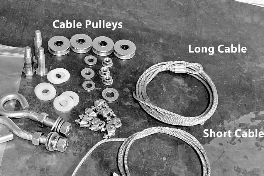
Installing the three lift cable pulley assemblies
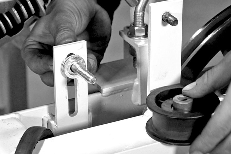
Unpack and lay out the cable pulleys and bolts as shown. There are two single cable pulleys, and one double cable pulley in the kit.
Take notice that one bolt is longer than the other two. The long one is for the double cable pulley assembly. (Be sure to use the nylon washers on the outside of each cable pulley.)
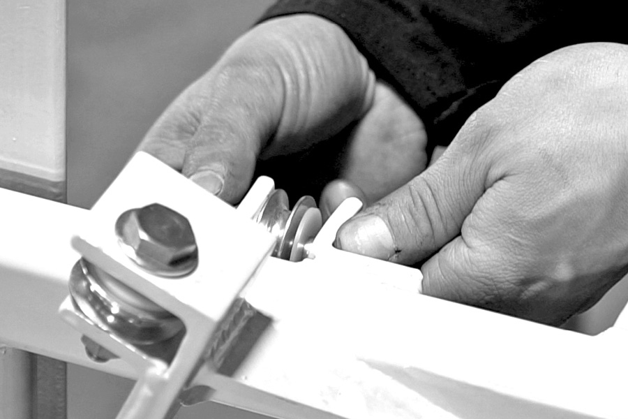
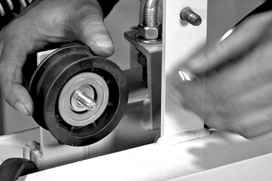
A. Install the first cable pulley in the bracket directly in front of the winch. Tighten securely. (Be sure that the pulley will turn after you tighten it.)
B. Install the next cable pulley just below to the side of the first one this is a single pulley also.
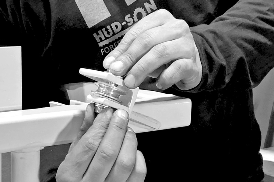
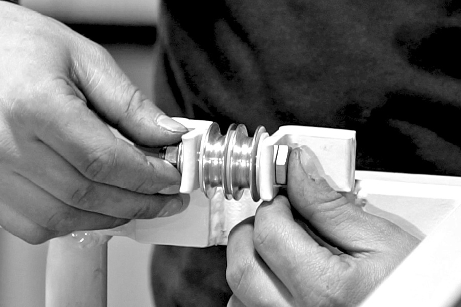
C. On the opposite side of the head you will be installing the double cable pulley. (Be sure to put the nylon washer between the two pulleys and one on each end of the pulleys.) Tighten securely and make sure they turn freely.
Step 3 (Video – 3:33)
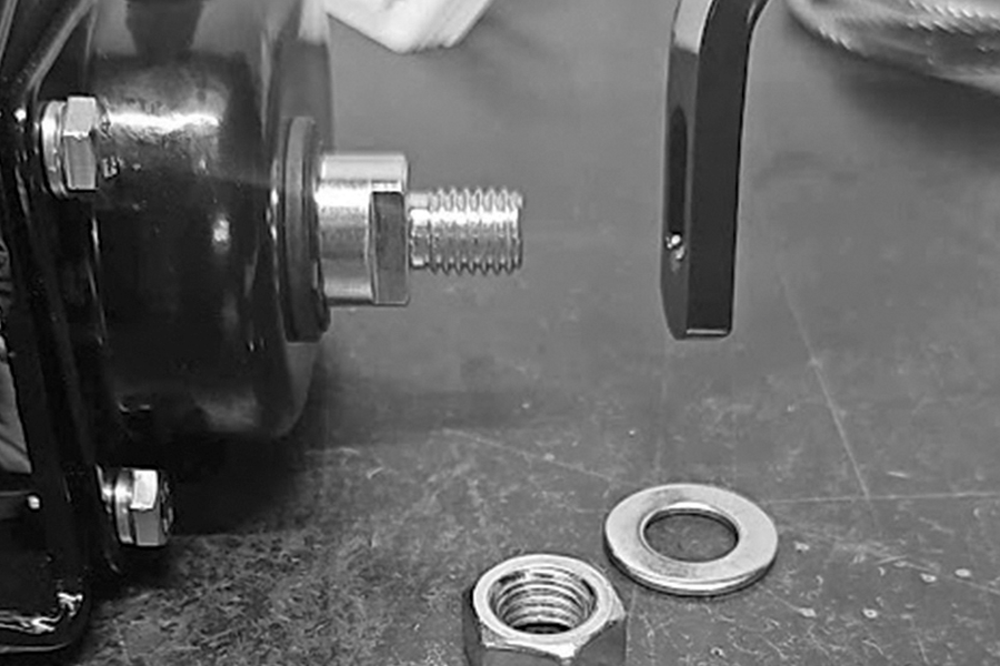
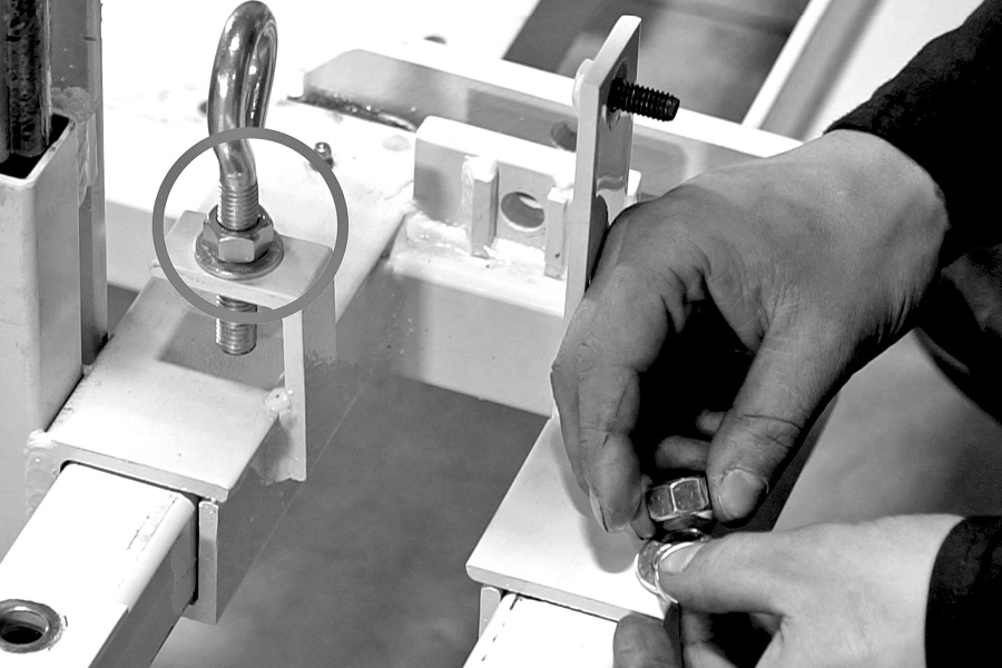
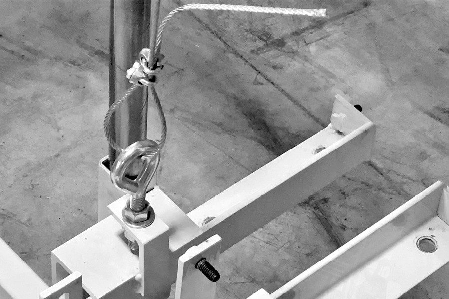
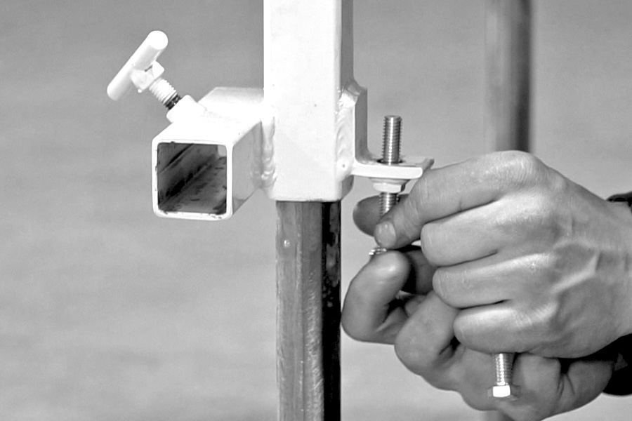
Installing the eyebolts
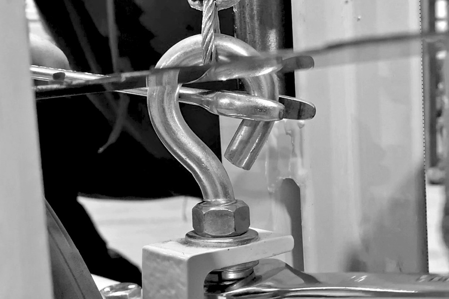
First, put a nut on each eyebolt, leaving about three quarters of an inch of threads exposed at the top of each eyebolt, then a flat washer. Install the eyebolts into the mounting brackets on the mill frame, put the flat washer, lock washer and nut on the eyebolts. Tighten them securely into place as shown.
Step 4 (Video – 4:00)
Installing the lift cables
Remove the zip tie on the winch drum holding the screw and nut. Thread the lock nut onto the screw finger tight. Put the screw into one of the bigger holes in the drum, with the hole facing the inside of the drum.
The lift cable kit has two cables in it, a long one and a short one. You will use the longer one first. Put the cable through the hole in the screw, leaving some slack.
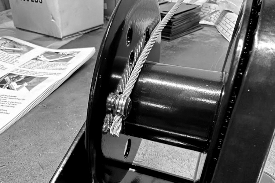
Thread cable from outside to inside, pull through and fasten eyelet end to outside of winch drum.
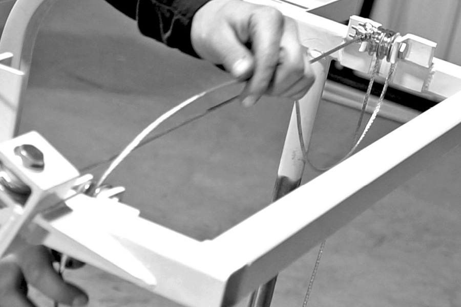
Next you will be threading the cable through the lift pulleys. First, go through the top pulley across from the winch, then over to left side pulley.
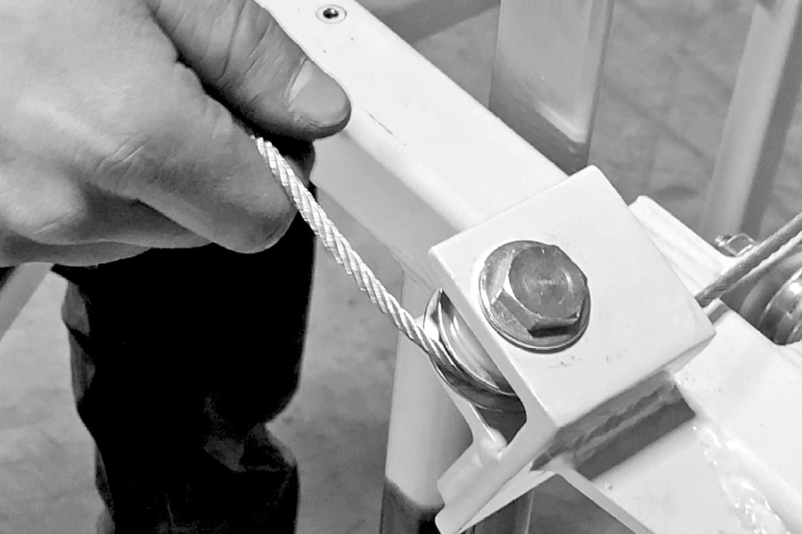
Then go down through the pulley on the right of the mill as you are standing on that side of the mill, straight down to the eyebolt,
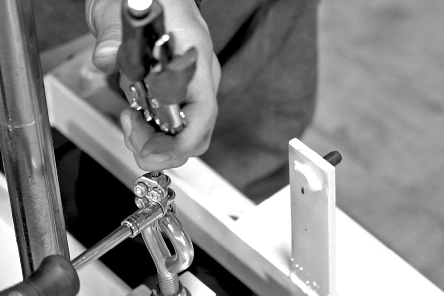
then slide two cable clamps onto the cable before passing cable through the eyebolt. Secure the running end of the cable with two cable clamps, hold in place and make sure both clamps are tight. Leave about 2 inches of the running end of the cable past the cable clamps, tighten clamps securely.
At this time hold the cable taught near the winch, crank the winch to draw the slack out of the cable, winding the cable on the winch drum accordingly.
Once you have this cable taught, secure three more cable clamps and put them on the cable that you just installed going across the top of the mill, as shown.
Secure the short cable, run it up from the bottom of the outside double pulley as shown. Using the three cable clamps all facing the same direction, secure that cable to the other cable leaving a tail about 1 1/2 inches long past the far clamp. Tighten all clamps leaving the clamp closest to the pulleys about 1 1/2 inches from the double pulley assembly. Now run the cable across the mill the down through the opposite side lift pulley to the other eyebolt on the opposite side of the mill.
Again slide the two cable clamps onto the cable before going through the eyebolt, then go through the eyebolt and back up to the cable, and secure it with the cable clamps.
[Note] Use vise grips to pull on the running end of the cable to remove any slack before tightening cable clamps.
After tightening clamps, cut off the running end of the cable and leave about 1 1/2 inches of tail past the clamp above the eyebolt.
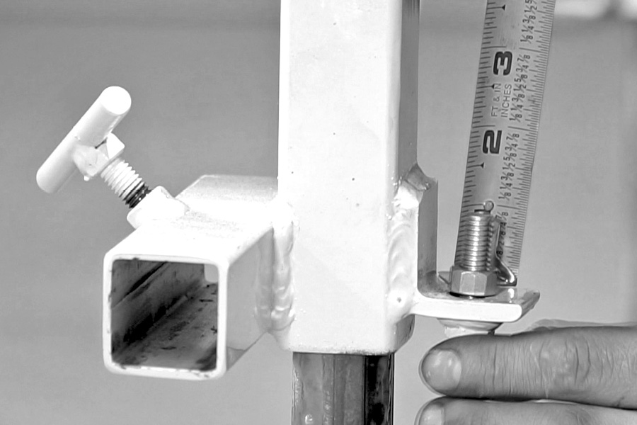
Step 5 (Video – 6:23)
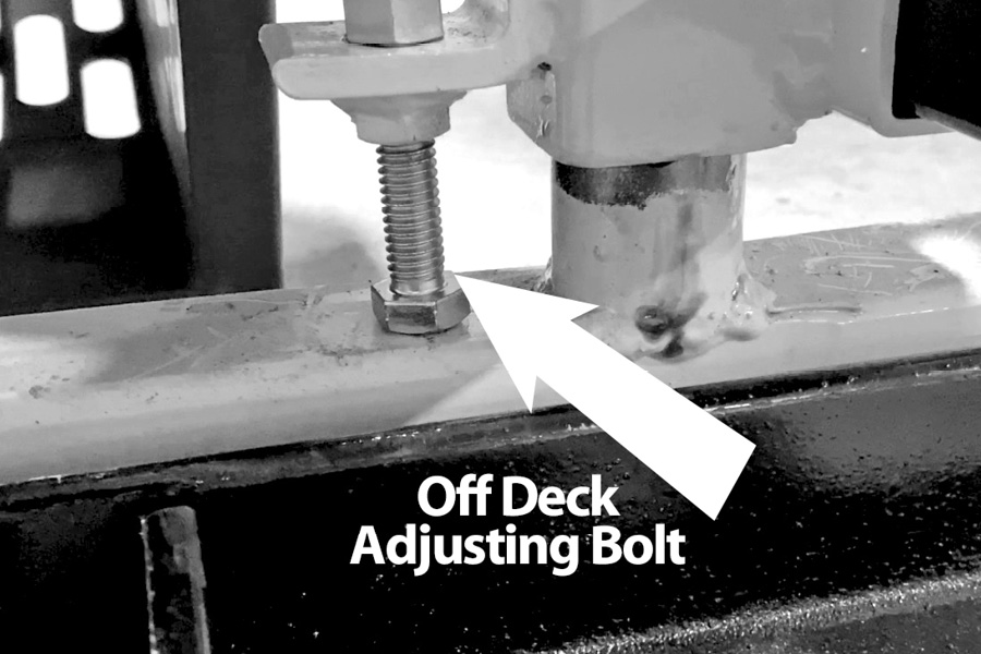
Installing the 1 inch off deck bolts
A. Crank the winch so that the head will go up roughly to the middle of the mill
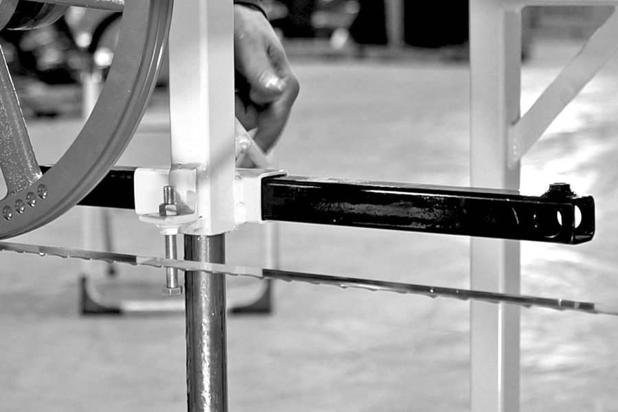
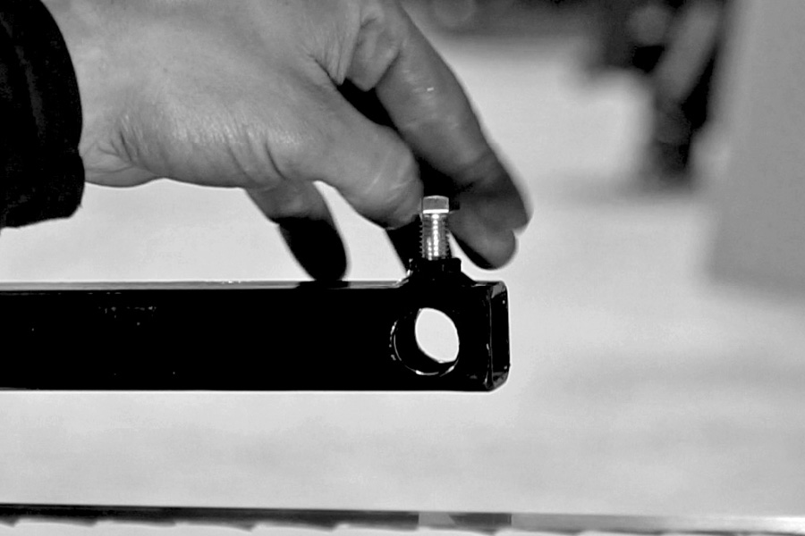
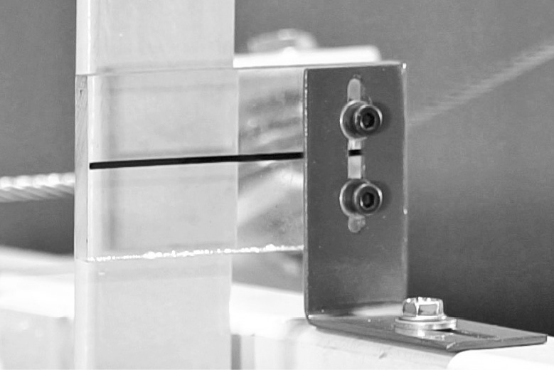
B. Thread the 1 inch off deck bolts in the bracket from the bottom up, leave about 1 1/2 inches between the end of the bolt to the machine frame as shown.
C. Install the locking jam nut, do not tighten, just snug firmly. (These will have to be adjusted later.)
[NOTE ] 1” of threads on top side of off deck bracket.
Step 6 (Video – 6:56)
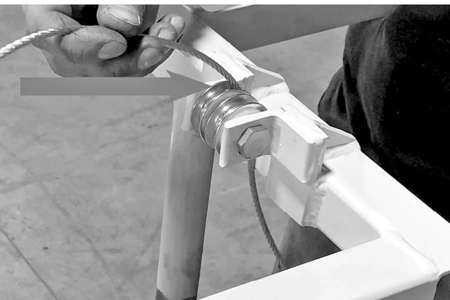
Install Blade tensioner bolt and grease fittings.
The tensioner bolt is the 1/2 inch by 4 inch long bolt, gold in color. In the kit, you’ll have 2 cup washers and a thrust bearing. Install the bolt first, then place first cup washer on the bolt with the smooth side toward the mill head, then the thrust washer goes on. Put a little grease on the thrust washer at this time to make it easier for adjusting blade tension. Put your second cup washer over the thrust bearing, Spin nut on, leaving about 1 inch of threads exposed from the end of the bolt at this time.
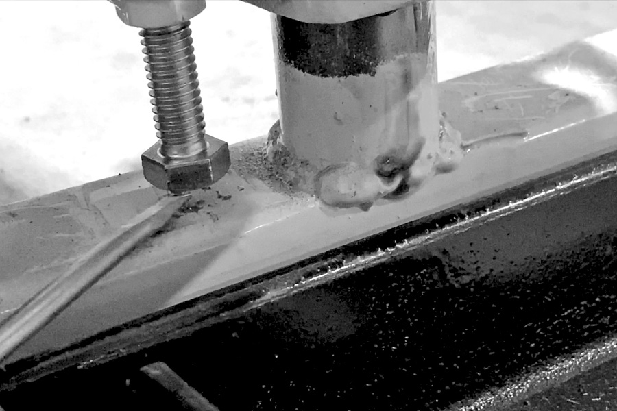
Secure the two Zürich grease fittings and install them into the predrilled holes on the slide rails of the head. Install the two Zurich grease fitting in the slide rails on the mill head, seat fitting in hole. Tap in with a piece of hard wood or dimpled punch. [see pic below]
Step 7 (Video – 7:39)
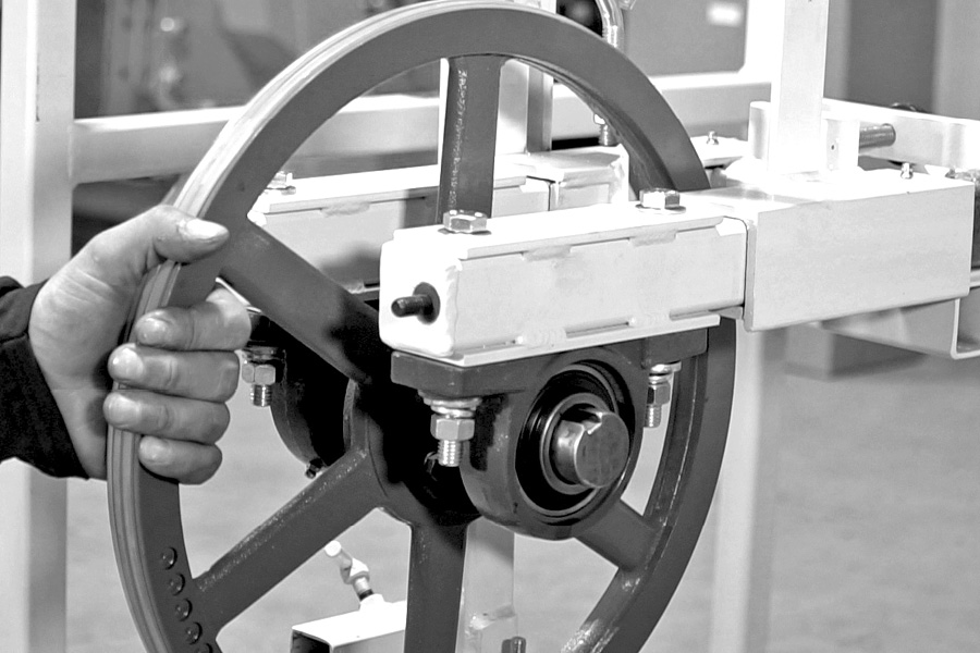
Installing main bearings and band wheels.
Install both band wheels with the center inside hub facing the front of the mill. Install band wheel on the adjustable side first, same side that the winch is on or operators side of the mill. Lay out hardware so it is easy to get when installing the bearings.Using the bolts provided, put a washer on each bolt first and drop into the main bearing bolt holes. Bring the pre-set band wheel assembly up to the bottom side of the mill head frame, line up the bearing bolt holes up to the bolts. Install flat washer, lock washer and nut. Make sure the wheel is setting square with the frame, then pull back on the wheel assembly as you snug the bolts up. Do not tighten bolts at this time just snug them up. Then check to see if the band wheel is plumb. If not, a shim will be needed under bearing.
Use the shims provided in the kit to bring band wheel to plumb as needed.
NOTE : [No more than 2(two) shims should be used under each bearing]
Next you will be installing the drive side band wheel pulley and bearing assembly. First, secure the drive belt and put the belt in between the band wheel mounts BEFORE putting the band wheel into place. Repeat the same steps as you did on the other side to mount the band wheel assembly in place.
Again, do not tighten bolts just snug them up and check for plumb. Shim under bearing if needed.
[NOTE: Put the belt on before installing the band wheel (drive side)]
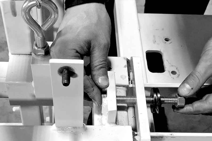
Step 8 (Video – 9:25)
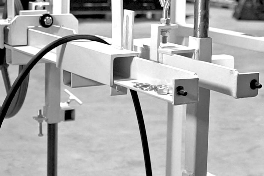
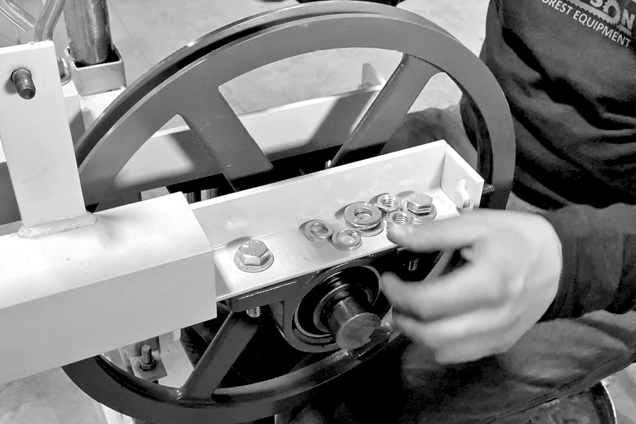
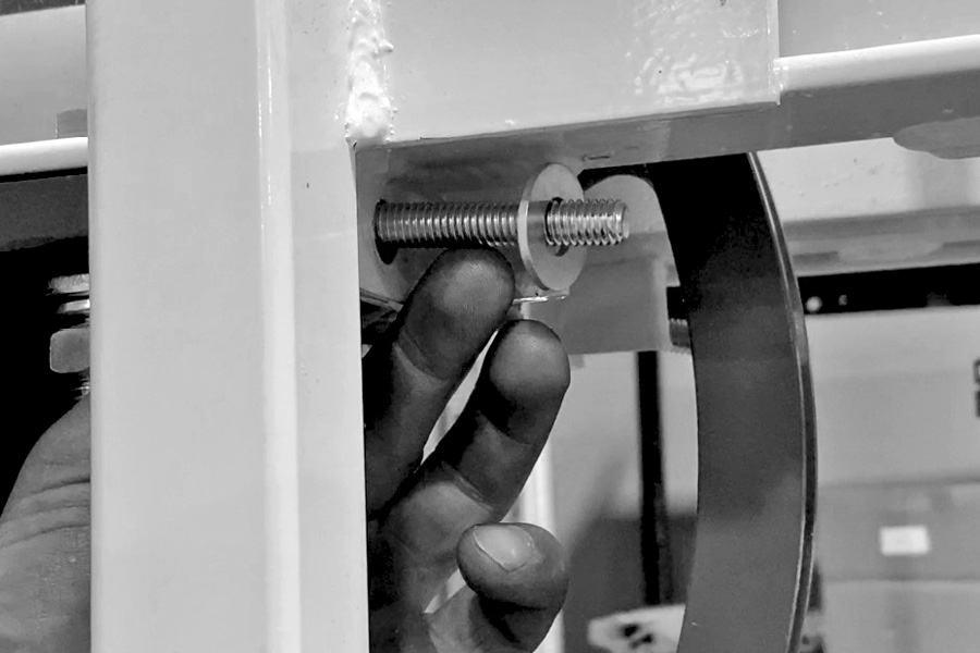
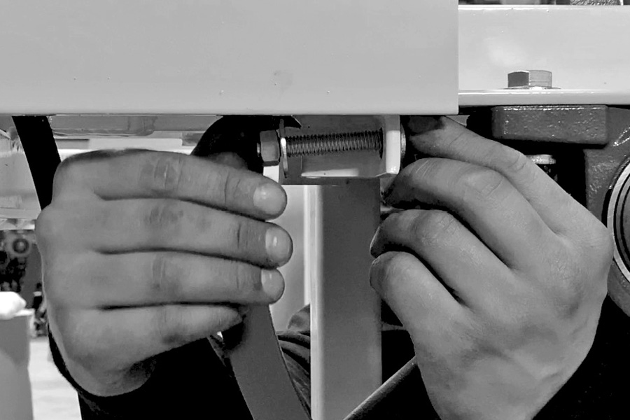
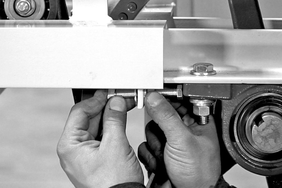
Install the main bearing adjusting bolts
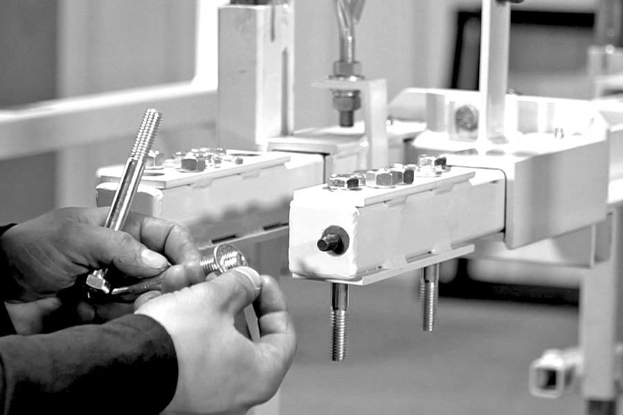
Locate the 2 adjusting bolts, install a nut on each one. Screw it on until it is about 1 inch from the head of the bolt. Do the same on both bolts, then put a washer on each bolt. Slide the bolt through the hole in the bracket in front of each bearing, then put on the washer and then the nut (hand tight) and leave them. You will tighten them up later after final adjustments have been made.
Step 9 (Video – 9:50)
Engine preparation
A. The engine comes completely assembled. You will just have to put the provided engine oil in it and install the clutch on to the crankshaft.
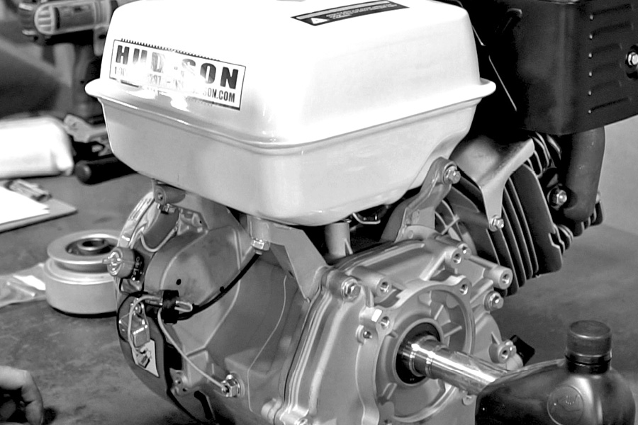
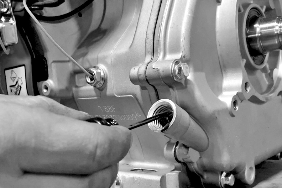
Remove the engine from the box and locate the quart of oil that was shipped with your engine. Make sure the drain plug is in the engine and then put the oil into the engine in the oil check port located on either side of the engine. Be sure to check oil level after putting oil in the engine to make sure it is up to the correct level.
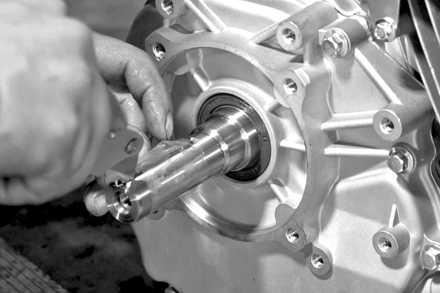
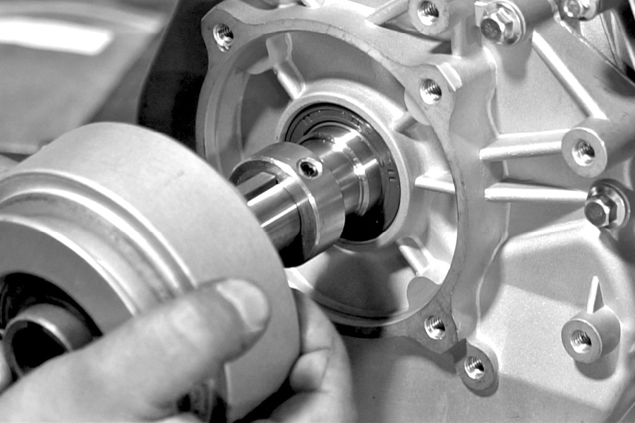
B. Installing the clutch.
Remove the shipping bolt tape and key from the crankshaft [Discard the shipping bolt and keep the key. Use this key with the clutch], then wipe down the shaft to remove any excess oil.
[NOTE: Use the Key shipped with the engine when installing the clutch.]
Next, locate the 1 inch clutch spacer shipped in your kit. Slide spacer onto the shaft and Loctite the set screw, tighten securely with Allen wrench.
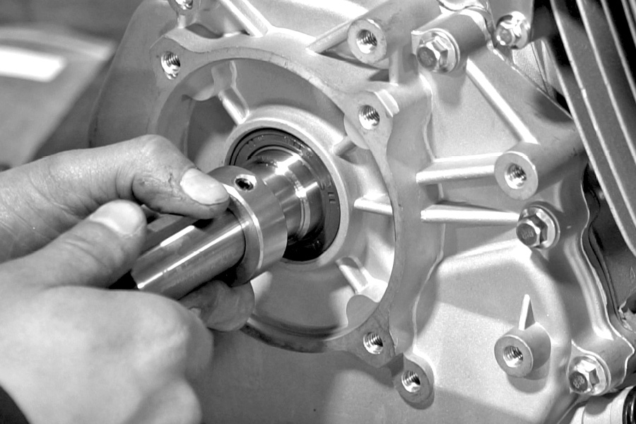
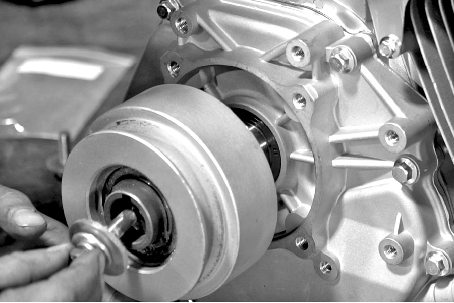
Next, you will put the key into the keyway on the shaft of the engine. Once the key is on the shaft, you can slide the clutch onto the shaft, lining up the keyway on the clutch. It should slide easily onto the shaft.
Finish installing the clutch. Secure the bolt lock washer, flat washer, and serrated washer from your kit. Use Loctite on the threads of the bolt, screw the bolt into the end of crankshaft and tighten securely but do not overtighten the bolt.
Step 10 (Video – 10:50)
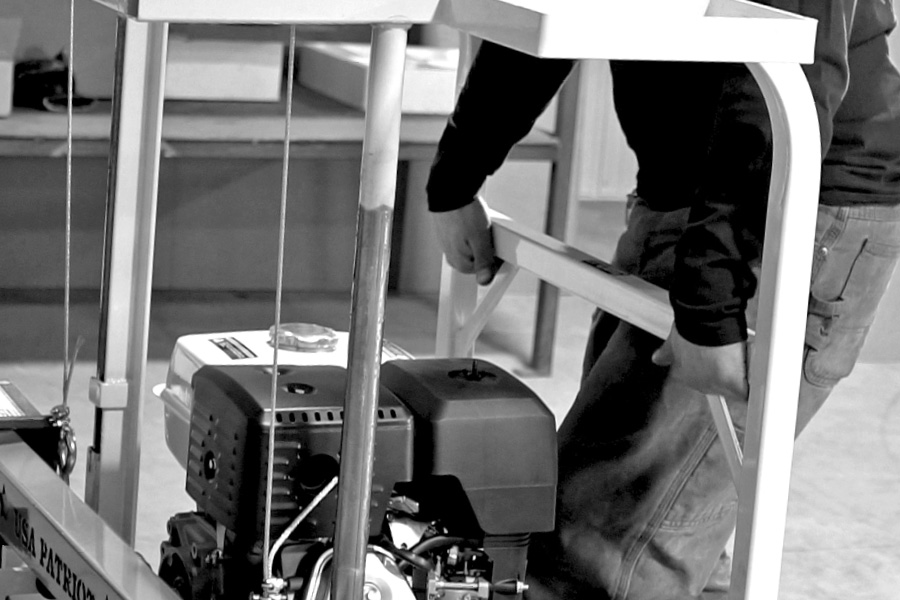
Mounting engine onto the mill head.
Set the engine onto the engine mounting plate of the mill head. Install all four of the engine bolts but do not tighten yet.
Slide the engine forward as far as it will go with bolts loose, keeping it square to the plate and frame, then tighten engine mounting bolt. Aligning of the band wheels and clutch must happen before you can tighten the engine securely into place.
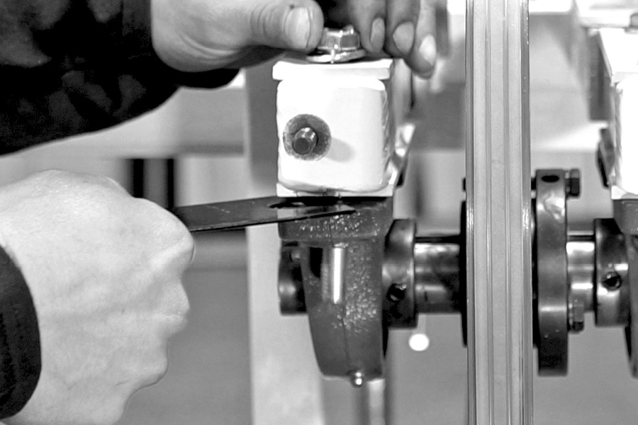
Run a straight edge across the drive band wheel and up to the clutch to get the correct belt alignment. The straightedge should be flush and square with the outside edge of the clutch, and flush and square to the outside edge of the drive band wheel.
Tighten the motor bolts once alignment is done, then recheck alignment after everything has been tightened.
Step 11 (Video – 11:32)
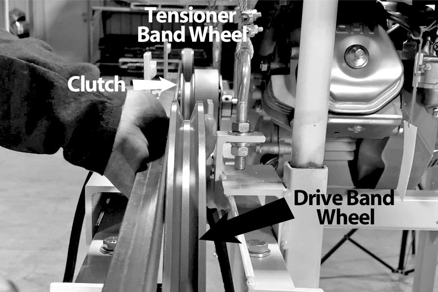
Installing belt tensioner pulley assembly
Locate your belt tensioner wheel and hardware kit. [Note: locate the smaller diameter washer, use that washer on the front side of the tensioner pulley]
· Put one flat washer onto the bolt
· Insert bolt into the bracket, then put two more washers on the bolt on the front side of the bracket.
· Then put the tensioner pulley onto the bolt, use the small washer and lock nut to finish the assembly.
· Tighten the idler pulley just below the half way point of the adjusting slot.
[NOTE: Keep in mind that you may need to add or subtract a washer BETWEEN THE BRACKET AND TENSIONER PULLEY. That will be determined after you put the belt on, to get the correct alignment on the belt tensioner wheel with the clutch and the drive band wheel.]
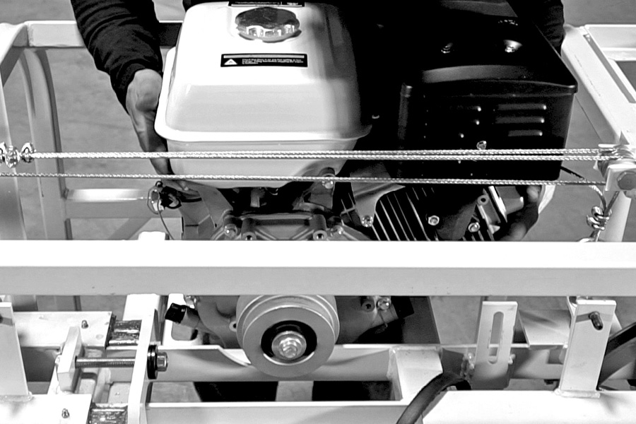
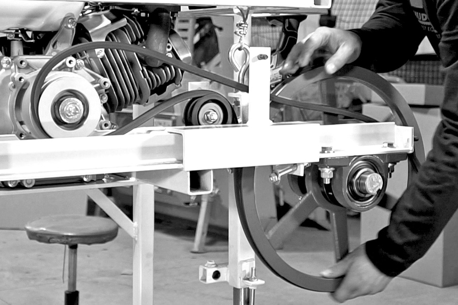
Now you will put the belt on to check alignment and tension. Start by looping one end around the clutch, over the top of the idler wheel, then bring it up around to the top of your band wheel. Roll the band wheel and the belt will run on the pulley. At this time, pull up on your belt tensioner wheel and snug the bolt up. Now turn the band wheel in the normal direction of travel to check alignment of the belt on your idler wheel. If the belt is going to one side or the other remove or add washers to either side of the tensioner pulley to bring the belt into the center of your idler pulley.
Adjusting the belt tension.
Secure the tensioner wheel about halfway down the bracket and snug into place. Install the belt on the clutch, run it under the idler pulley and bring it up from the bottom of the band wheel turning it into the pulley to run it on. When the belt is nearing the top of the pulley as you run it on, there should be approximately a two finger space between the top of the belt and the bottom of the inside of the pulley. If the belt is too loose at this point, loosen your tensioner pulley up and move it about a quarter of an inch, re-tighten the tensioner wheel and check it again. Then run the belt on and check the tension. You’re looking for one half of an inch to no more than 1 inch of free play on the belt. Adjust accordingly as needed.
Step 12 (Video – 13:06)
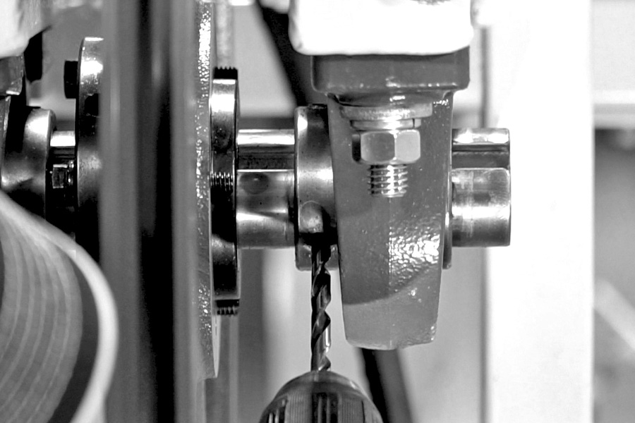
Lock bearings to shaft
Each bearing has two set screws on the collar. Remove one set screw from each bearing collar and Loctite the threads and put back into the bearing collar. Tighten securely. Remove the other set screw on the bearing collar. This one will be drilled and counter sunk into the shaft. This prevents the shaft from walking during operation.
You’ll need to use a 3/16 inch drill to countersink shaft for the set screws. One on each bearing will be countersunk. Now drill into the shaft approximately 1/8 of an inch to create a dimple for the set screw to set into. Loctite the set screw, and replace into the bearing collar and tighten it to the shaft.
You need to do this on both sides of the machine.
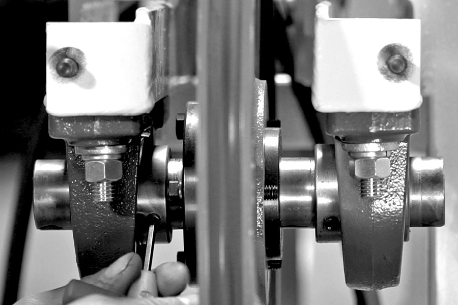
Drill and counter sink one set screw on each bearing collar. Loctite the other one.
Step 13 (Video – 14:51)
Add fuel and test the engine
Use non-ethanol gasoline only!
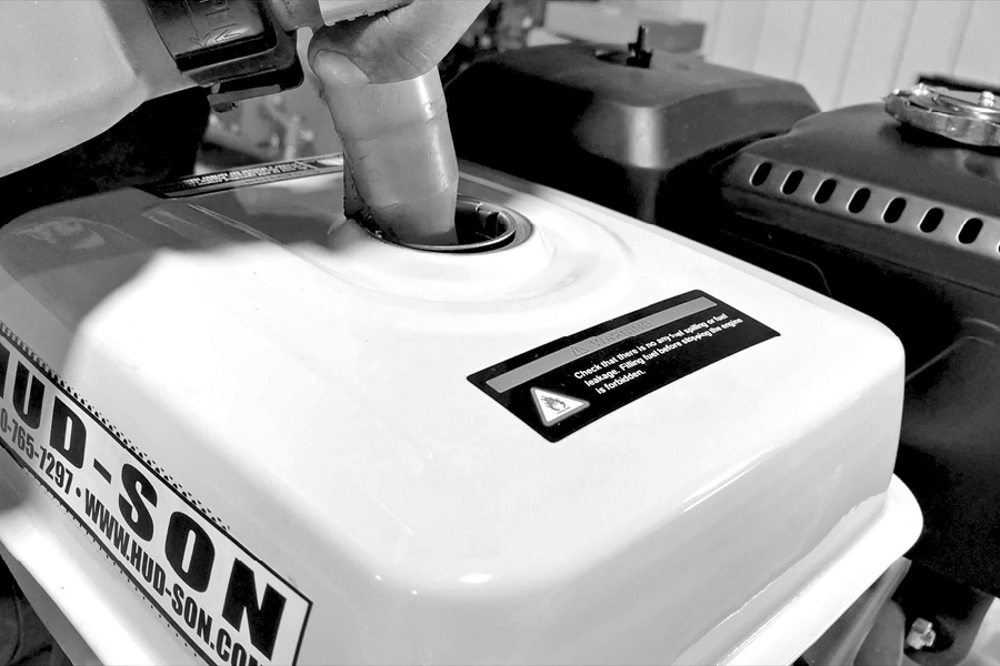
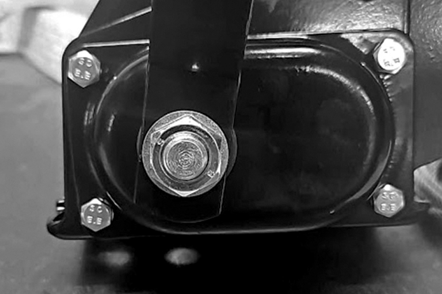
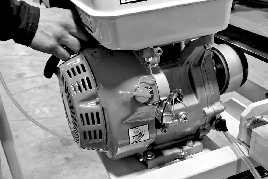
Once you have put fuel in the engine, turn the engine switch to the on position. Make sure the fuel shutoff is in the on position, put the choke in the choke position, and pull the recoil rope to start engine. Once the engine starts to move, choke forward to the off choke position and let the engine idle for a minute or two.
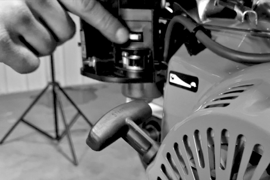
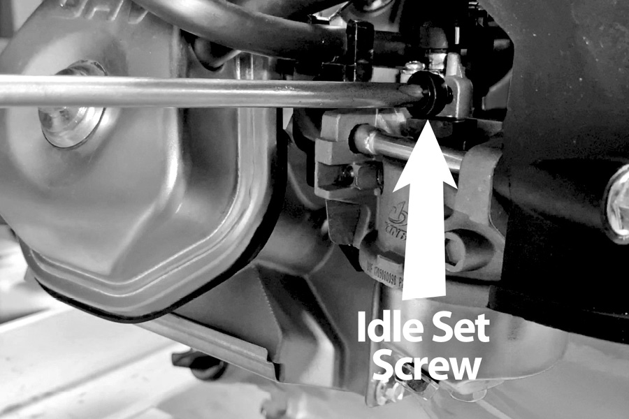
Move the throttle lever forward to the full throttle position. Keep your hands clear and any loose clothing from the moving parts. At this time, look at the belt and make sure that it is aligned properly. The belt should be centered on the idler wheel, if the belt rolls or flips on the pulley at this time, you will have to do a realignment on the idler pulley or remove or add a washer on the backside of the idler pulley. After running full throttle for about a minute, move the throttle all the way down to the idle position. At this time the belt should not be turning. If the band wheel is still turning on low idle, you will have to adjust the engine idle screw, as shown in the picture. Back the screw out to slow the engine down until the wheel stops turning. The idle is set. Turn the engine off.
Step 14 (Video – 16:03)
Installing the blade
Use a good pair of leather gloves when handling the band saw blades.
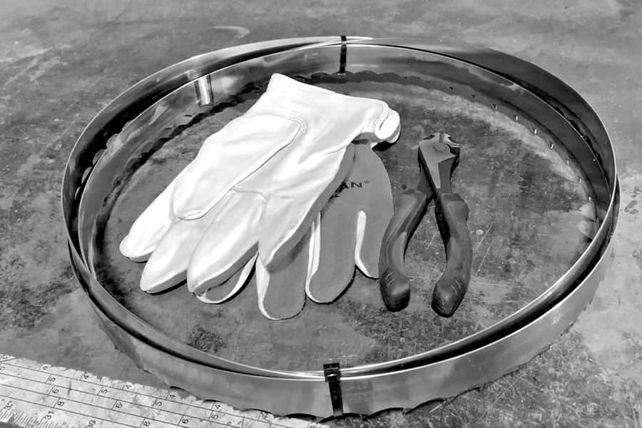
Be careful when uncoiling the band saw blade. The band saw blade is very sharp.
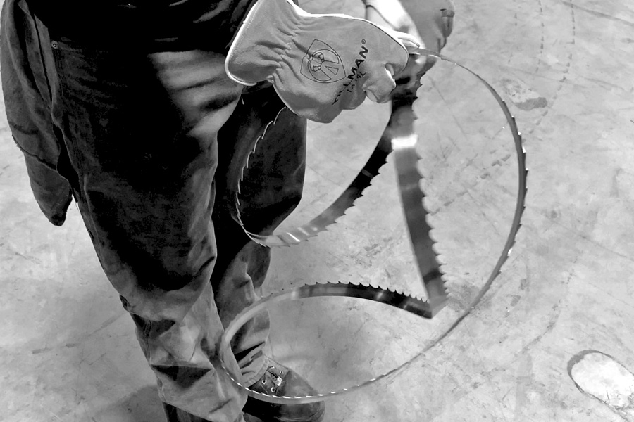
When installing the blade, make sure the teeth are pointing away from the engine.
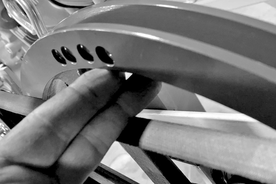
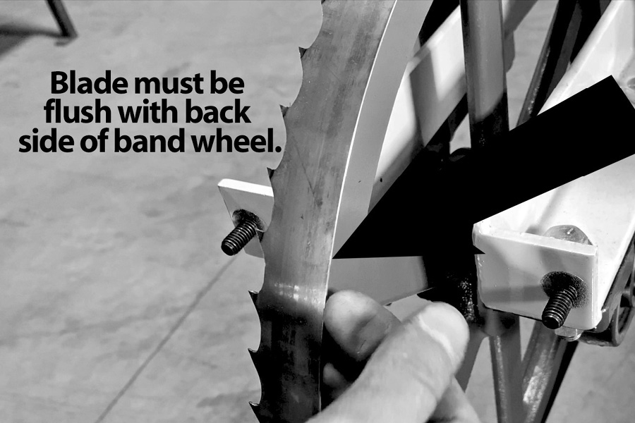
The backside of the blade should be flush with the backside of the band wheel on both band wheels.
Once the blade is on and is flush with the back side of both of the band wheels, you will need to tension the blade.
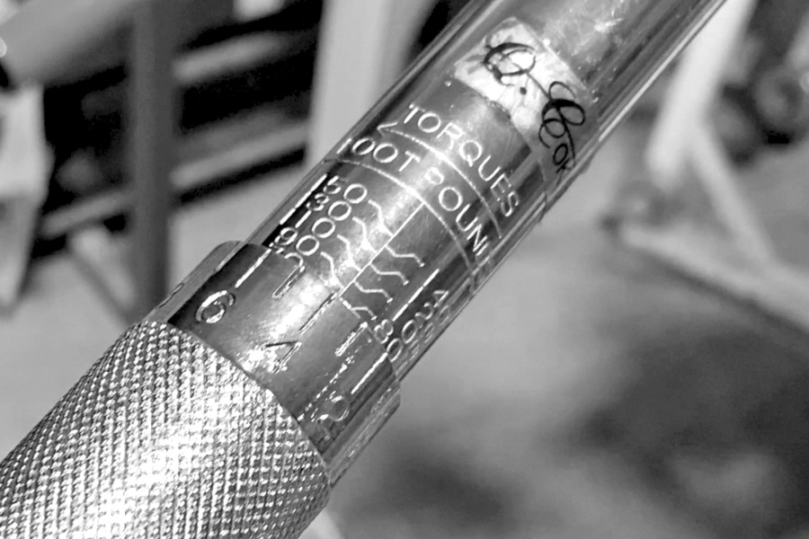
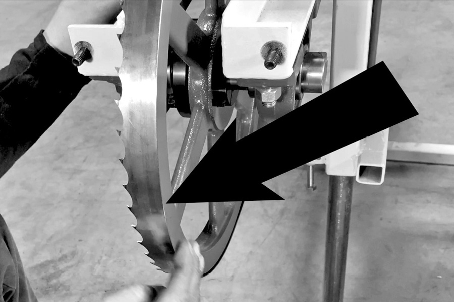
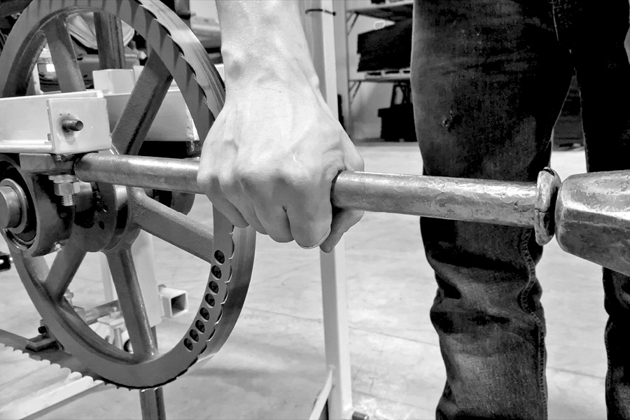
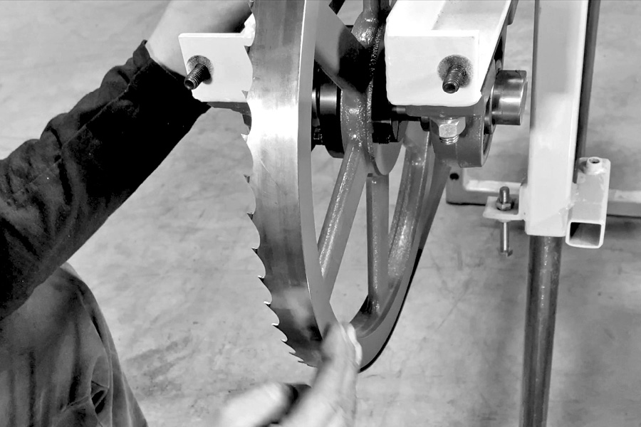
Set your torque wrench at 35 foot pounds and tighten the blade tensioner bolt to 35 foot pounds. Once you have the torque set, turn the band wheel by hand in the normal direction of travel, at least 5 complete revolutions. Now, check the backside of your band wheels. If there is a lip on the back edge of the band wheel, adjust the band wheel by tapping the bearing with a hammer and punch to move it into alignment.
Adjust the band wheel by tapping the bearing with a hammer and punch to move it into alignment.
[NOTE: YOU MAY ONLY HAVE TO MOVE THE BEARING A FRACTION OF AND INCH TO GET ALIGNMENT TRUE.]
Tap the bearing on the side that you need the blade to move in.
Rotate the band wheel in the normal direction of travel several times again, then check the back edge of your blade for alignment again.
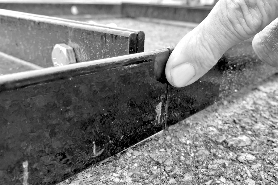
The back edge of the band blade should be smooth with the backside of the band wheels as shown here in the picture below. [be sure to turn the band wheel by hand in the normal direction of travel at least 5 complete revolutions, again and check both band wheels]
Once you have completed the alignment, it’s now time to torque the bearing bolts. Torque all eight of them to 74 foot-pounds.
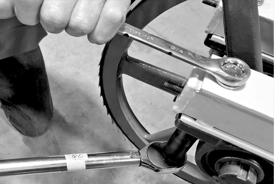 Now it’s time to set your bearing adjustment bolts in place. Be sure the head of the bolt is up against the bearing, then tighten the two [2] jam nuts up against the bracket. This will ensure that the bearing cannot move. If you need to make minor adjustments to align the band wheels, remember to loosen your bearing bolts before you do any adjusting.
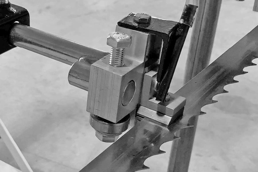
Step 15 (Video – 17:53)
Install blade guides
Layout your blade guide kit.
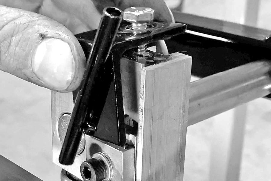
Secure the long black bar. The end with the hole in it goes toward the center of the mill, the hole needs to be horizontal when you install it, with the welded nut pointed upward (as shown below). Slide the guide bar into the adjustable guide bracket with the T handle on it, which is located on the operator side of the sawmill.
Screw set bolt into the top of the guide bar bracket.
Insert the long end of the guide pin so the short side L shape of the guide pin is going upward toward the outside of the mill.
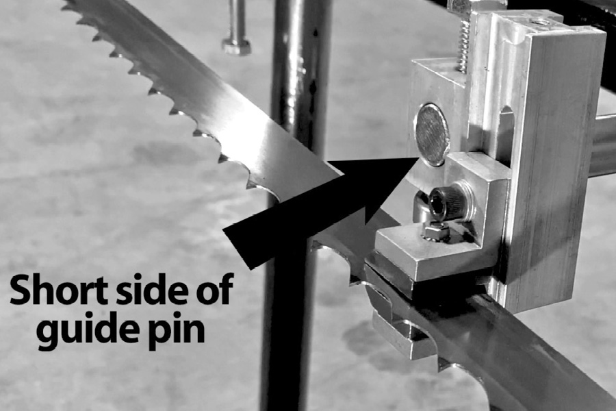
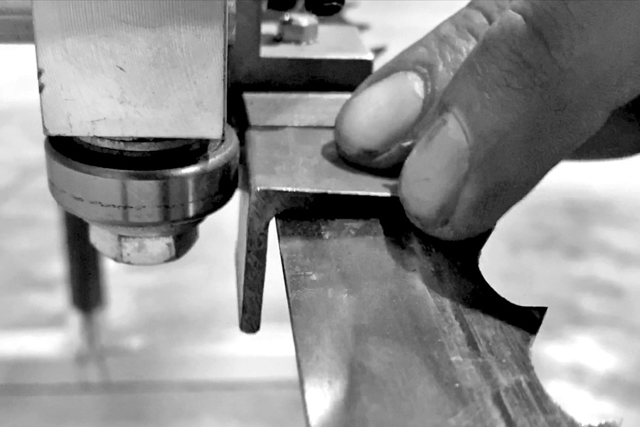
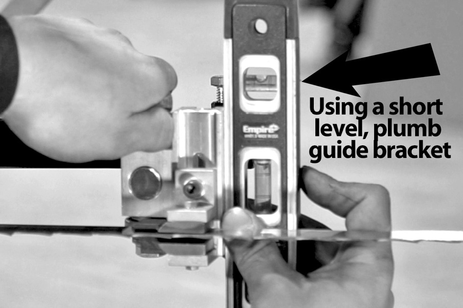
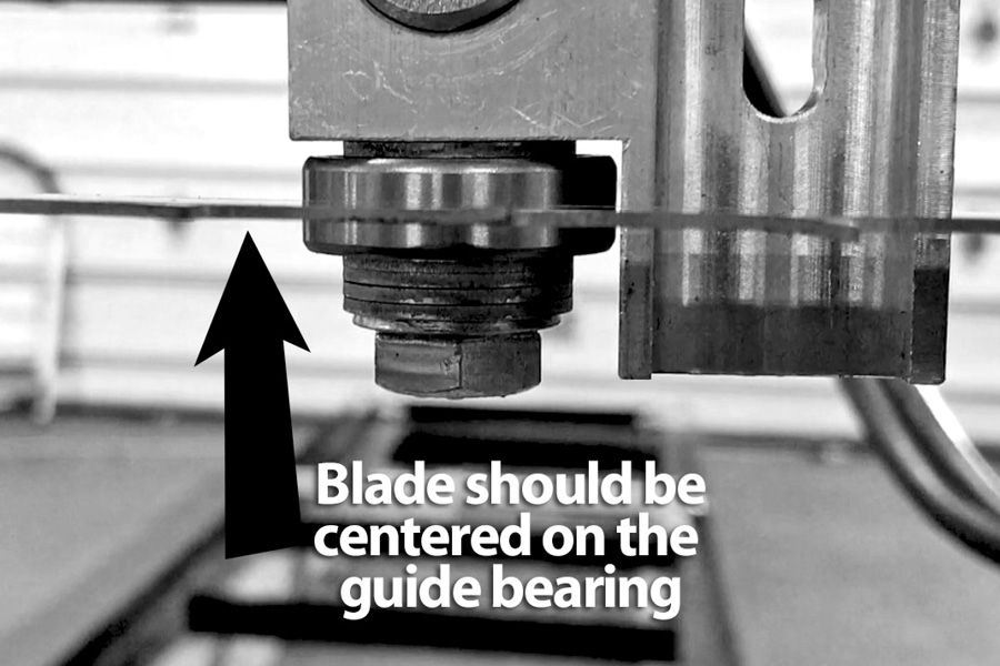
Slide the guide assembly onto the end of the pin, then slide the guide onto the blade leaving a 1/8 of an inch gap between the back of the blade and the guide bearing. You can use a short piece of 1/8 inch angle iron for this as a gauge.
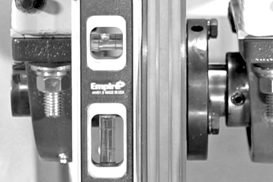
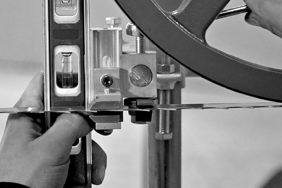
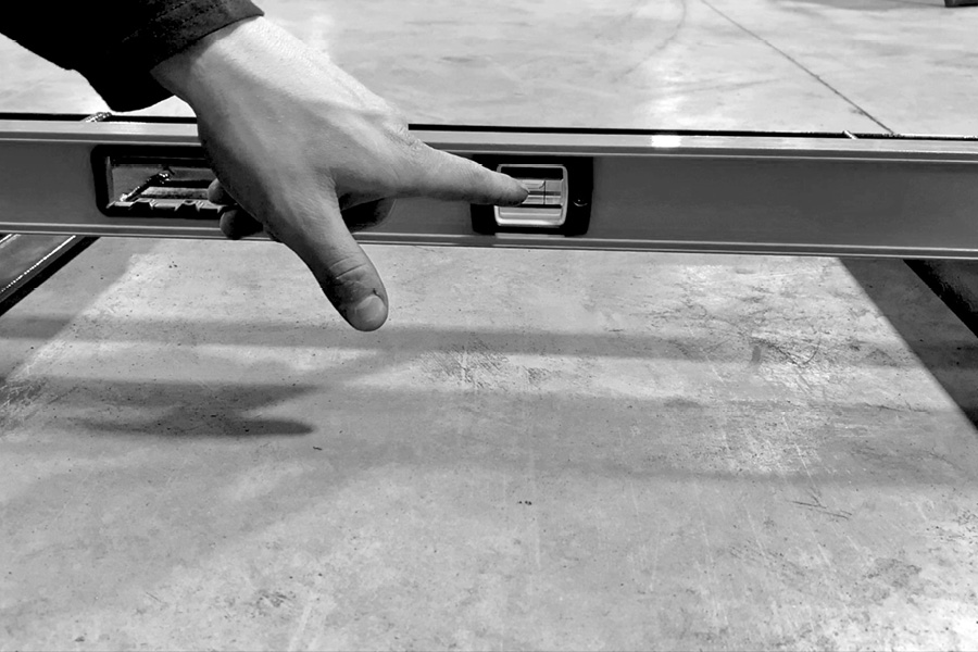
The guide bracket should be plumbed using a short level as shown below. The blade should be centered on the guide bearing as shown here.
To adjust the guide shoes, loosen the Allen screw on the front of the guide. Gently push dog guide shoe to the blade (be sure not to pinch the blade), then re-tighten the Allen screw. You can use a piece of paper or a dollar bill between the guide shoe and the blade as a gauge.
Make sure that the blade moves freely through the guide shoes.
Install the lube bracket. It mounts on the top of the movable guide assembly.
Now we will install the fixed guide on the opposite side of the sawmill.
Following the same steps as you did installing the first guide assembly;
Once your guides have been set, be sure to tighten all the bolts securely.
The guide assembly should look like this when completed.
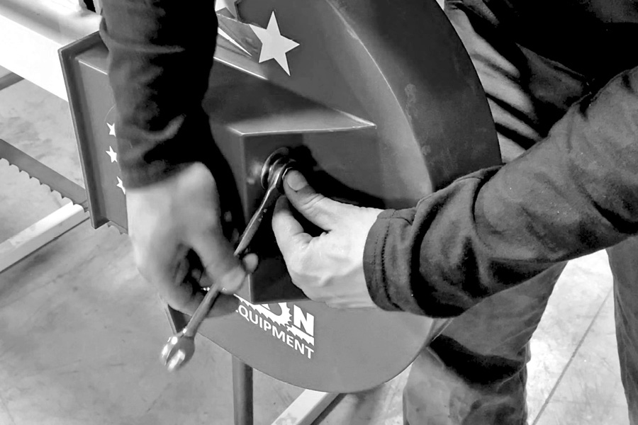
Step 16 (Video – 19:53)
Install the end guards and blade guards
It is best to install the decals on your guards prior to mounting them on the sawmill.
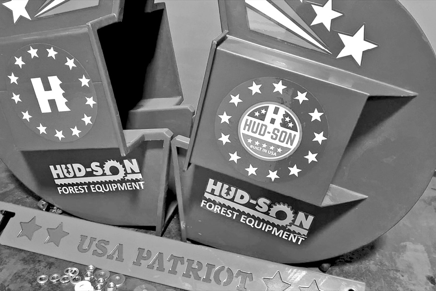
Locate the plastic washers from your hardware kit and put them on the studs before installing the blade guard plate. Set the blue guard over the studs and then put the red guard over the top of that, put the nuts on and tighten them. Slide the end guard on the studs and secure them using the big washer, lock washer and nut. Snug nuts up good but do not over tighten.
Step 17 (Video – 20:42)
Mounting the track wheels
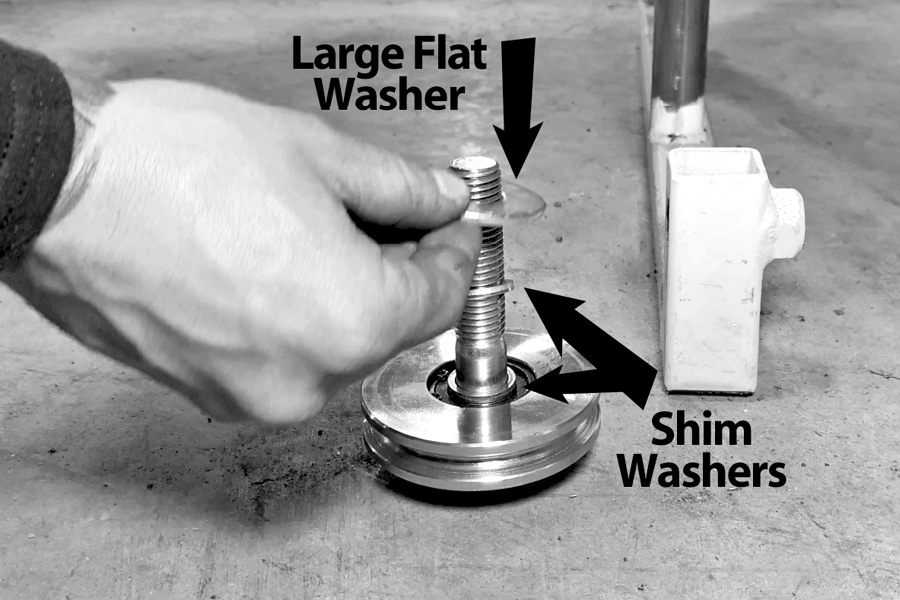
Lay out the track wheel hardware and track wheels, track bolts, shim washers, and washers. [Put a couple drops of oil on the bolt threads]
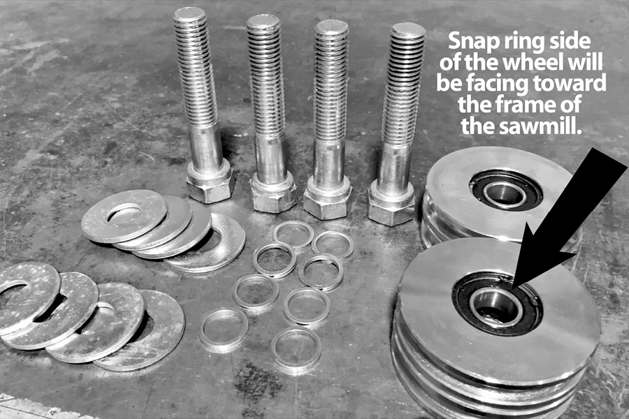
Look at the track wheels; there is a snap ring that holds in the bearing on one side of each wheel. That side of the wheel will be facing inward toward the center of the sawmill. [Track wheel bolt head will be on this side of track wheel.] Slide the track wheel onto the bolt, snap ring side of the wheel facing the head of the bolt. Put on [2] shim washers and then the large flat washer.
[NOTE: If you need to remove a washer, remove the large one. You may have a couple of spare large washers and we ship extras if needed.]
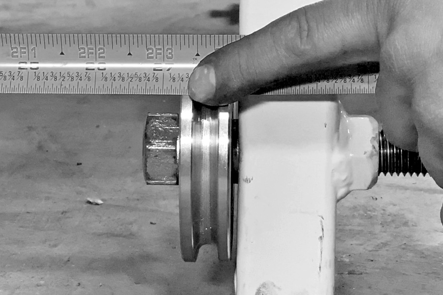
Screw the bolt and wheel assembly into the track wheel hole on the mill frame and tighten the track wheel bolt securely. Do this to install all four track wheels. After mounting all the track wheels, you will need to check the distance between the track wheels. The distance should be 27 ¼ inches across from the outside edge of one track wheel to the inside edge of the other track wheel.
If the distance is incorrect, remove or add a shim where it is needed. Check both ends of the mill.
[ NOTE: If removing a shim is necessary on the front and rear wheels, remove or add the shim on the same side of the mill head.]
Step 18 (Video – 22:17)
Track assembly
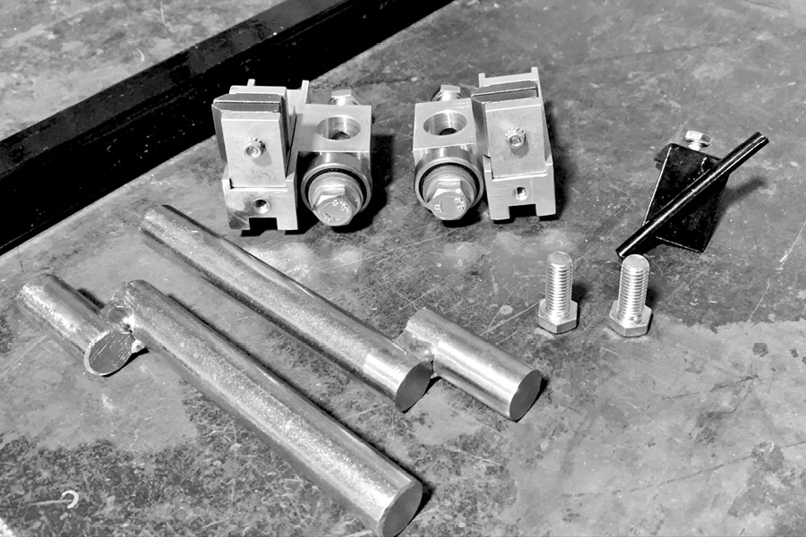
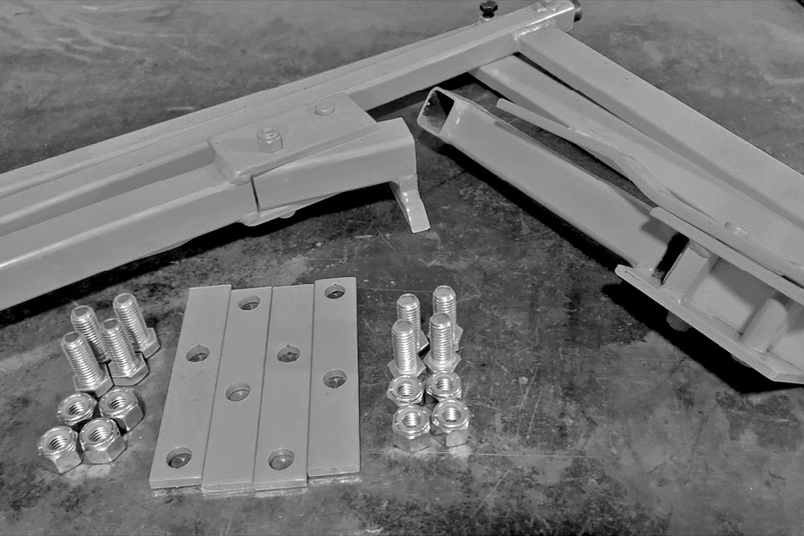
Locate the track hardware kit. It should include four track stop tabs, eight half-inch bolts with nuts, 2 backstop J bars, 2 moveable dogs, and two ¾ inch rods.
Lay the two six-foot sections of track end-to-end on the floor. Make sure the back stop tabs are on the same side.
Using the bolts provided, bolt the two sections of track together making sure that the top of both sections are perfectly flush where they come together on the side rails.
Do not tighten the bolts just snug them at this time.
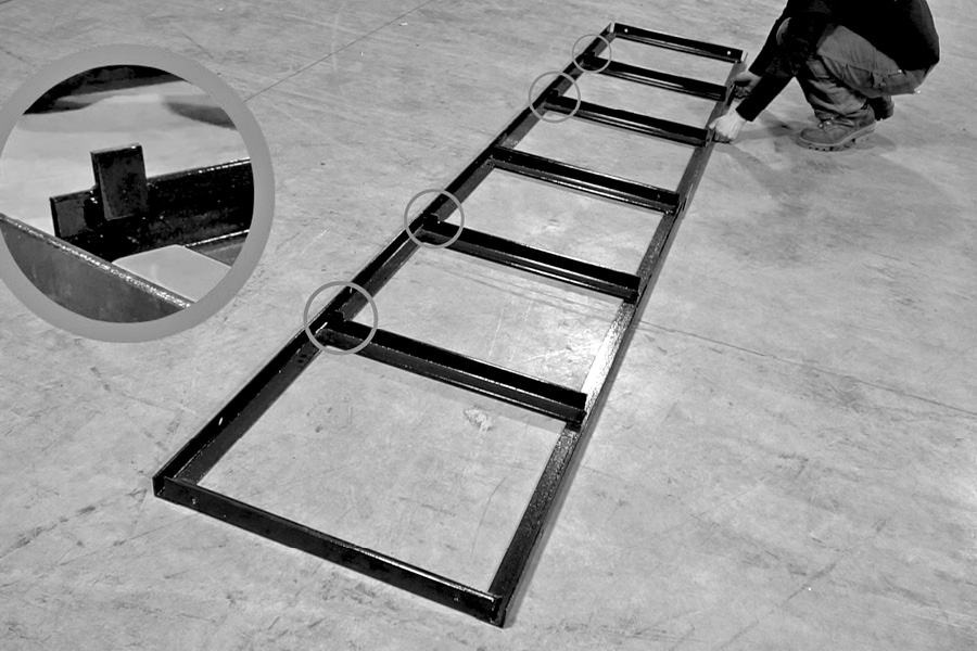
Check your track to make sure it is level. When setting a track up outside, blocking in shimming will be required to achieve levelness of the sawmill track.
Always be sure that the top and edges are flush and smooth before tightening the track sections all the way.
Step 19 (Video – 23:40)
Install log dogs
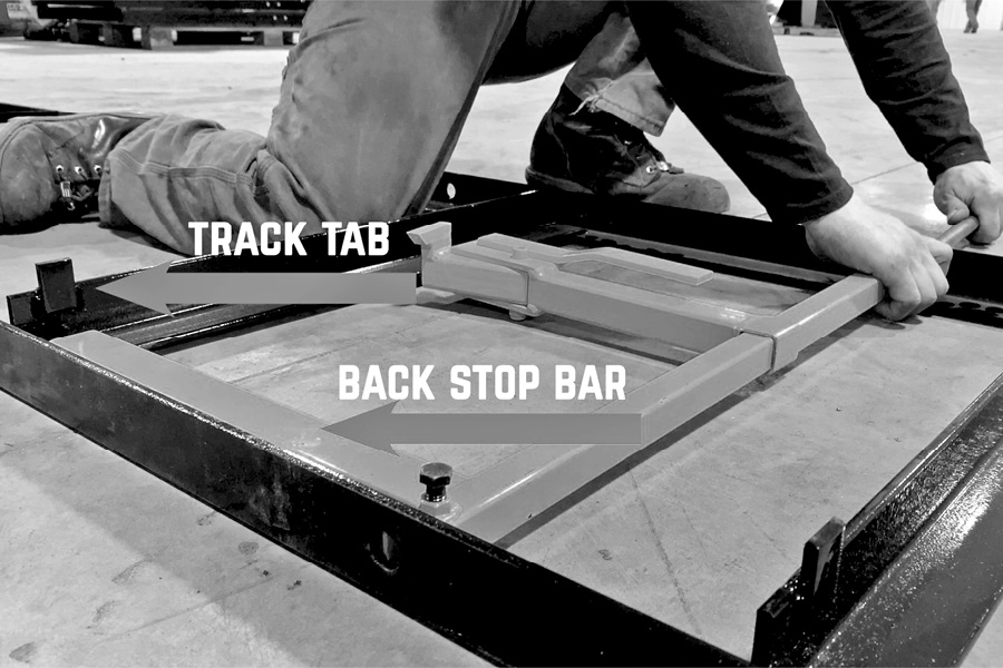
Slide the movable log dog onto the backstop bar with the point of the dog facing the backstop.
Set that assembly in your track at your desired location. Make sure to put the backstop bar of the dog assembly on the same side of the track as the track stop tabs that are welded in your track frame.
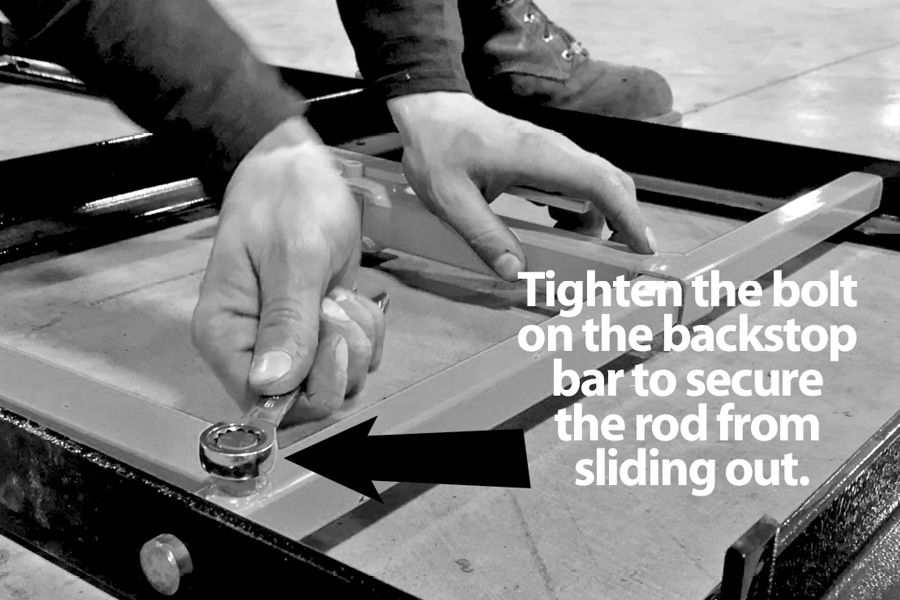
Then slide the ¾ inch rod through the track frame hole into the backstop tube and then into the other side of the track frame.
Set the rod so that the ends of the rod protrude from each side of the track evenly, which should be about 1/8 to 1/4 of an inch on each side.
Then tighten the bolt on the backstop bar to secure the rod from sliding out, now raise and lower the dog and make sure that it moves freely up and down. Repeat the same steps to install the second dog at your desired location.
Once you have the track frame assembled, you will now install the track stop tabs at the ends of the track. These prevent your mill from running off the track during use. Using the provided hardware bolt and one track stop at each corner of the mill track as shown. [snug bolts up firmly]
Leave the stop tabs loose at the end you are going to put the mill on. Flip them inward not to block the track so you can roll the mill on the track. When the mill is on the track flip back outward and snug bolts up firmly.
Step 20 (Video – 24:52)
Placing the mill on the track
Raise the head approximately 3 inches before attempting to set the mill head on the track.
Set the mill in front of the track. The operator side of the mill will be on the side of the track with the movable log dog. With the wheels lined up at the end of the track, lift the front of the mill and set the first two wheels onto the track.
Then go to the other side of the mill, raise it up and move it forward until the other two wheels roll up onto the track. Be sure to lift with your legs and not your back. Once you have the mill set on the track you will flip out the track stop tabs at the end of the track. These prevent your mill from running off the track and getting damaged.
Step 21 (Video – 25:51)
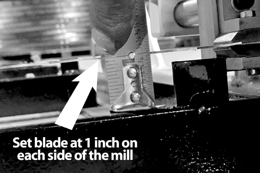
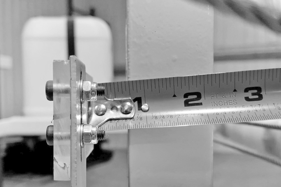
Set the blade to 1 inch off deck
Move the sawmill down the track until the blade is lined up over one of the cross members of the track. The blade should still be tensioned at 35 foot pounds and the head should be set all the way down. Measure up from the cross member of the track to the bottom side of the blade. The distance there should be set at 1 inch on each side of the mill.
If it does not measure 1 inch, you will make the adjustment using the off deck bolts that you installed earlier on each side of the mill head.
Raise or lower the mill head on either side using the adjusting bolt, once you have both sides at the same measurement. Use the jam nut to lock the adjusting bolt in place.
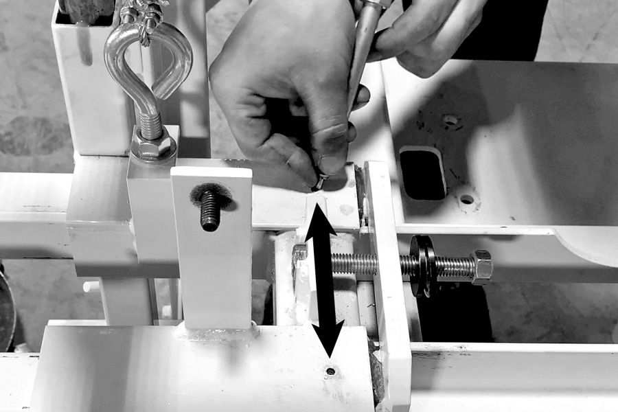
Step 22 (Video – 26:16)
Make sure each side of the head raises together
After setting the off deck adjustment bolts, you need to make sure that the head rises evenly on both sides to ensure square cuts.
To check this, start raising the head slowly with the winch and watch the head to see if it lifts evenly on both sides at the same time. If it does, you’re okay. If it does not, adjustments need to be made. If you notice that when lowering the head one side will touch the frame first and the other side will have a gap until you lower it all the way.
If the mill head does not raise and lower evenly: You will need to make adjustments at the eyebolts. To make the adjustment, determine which side is touching first, then lower the head until that one just starts to touch the frame. Now go to the side that is not touching, remove the band wheel guard so it is easier to get to the eyebolt nuts to make the adjustment.
Loosen the bottom nut on the eyebolt, as you unscrew the bottom nut the head will lower on that side. When the off deck bolt starts touching the frame, stop! Then screw the top nut down on the eyebolt and lock it into position again. Now the mill head should raise evenly on both sides.
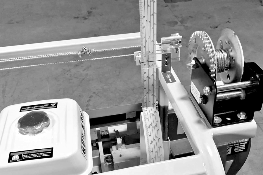
Check it again to ensure that the head is raising and lowering evenly. You can also check this by looking at the scale bar. As you raise the head up from the bottom if the scale bar goes left or right, one side is raising before the other. If you see that, make the necessary adjustments on the eyebolts.
Step 23 (Video – 28:20)
Install push bar and scale sticker and sight glass
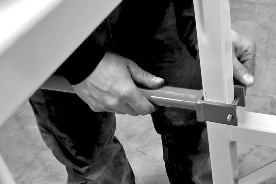
Attach the push bar to the operator side of the frame with the supplied hardware.
Attach the sight glass.
It should be mounted approximately 3/4 inch in front of the scale bar.
Centered on the top of the frame as shown, using the provided self-tapping screw. It is best to drill an 1/8 inch pilot hole for the screw. Be careful not to over tighten and twist off the screw.
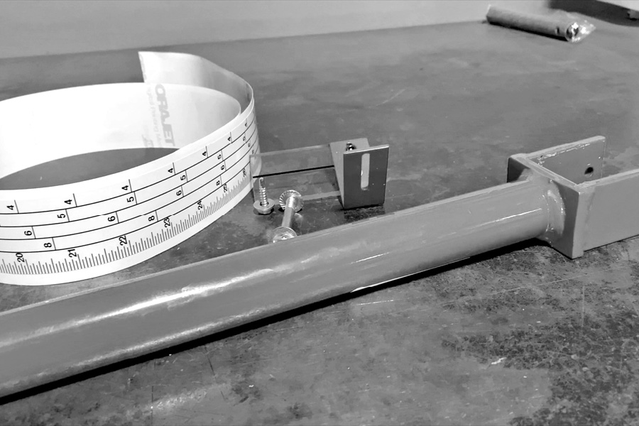
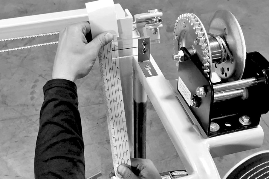
Next install the scale ruler.
It is best to clean the bar off prior to installing the sticker to ensure adhesion. (Remove any oil or grease.)
Lower the head all the way down, peel the backing from the adhesive tape starting at the top. Do not peel off too much to get started.
Align the sight glass black line with the 1 inch mark on scale sticker.
Center the scale sticker on the bar, remove backing as you adhere it to the bar.
Be careful not to stretch the sticker when installing.
To make it easier, raise the head as you’re adhering the sticker to the bar. This will help you keep it straight and get good adhesion.
The sticker is wider than the bar, so roll the edges around the bar.
Cut the scale sticker off at the 28 inch mark.
Step 24 (Video – 29:50)
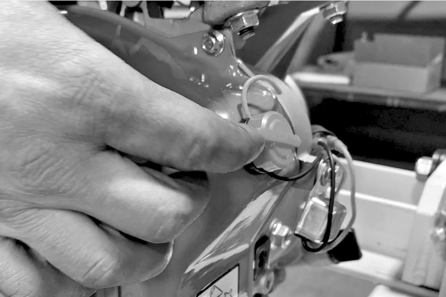
Installing the lube tank system and line.
Locate the lube tank hardware kit.
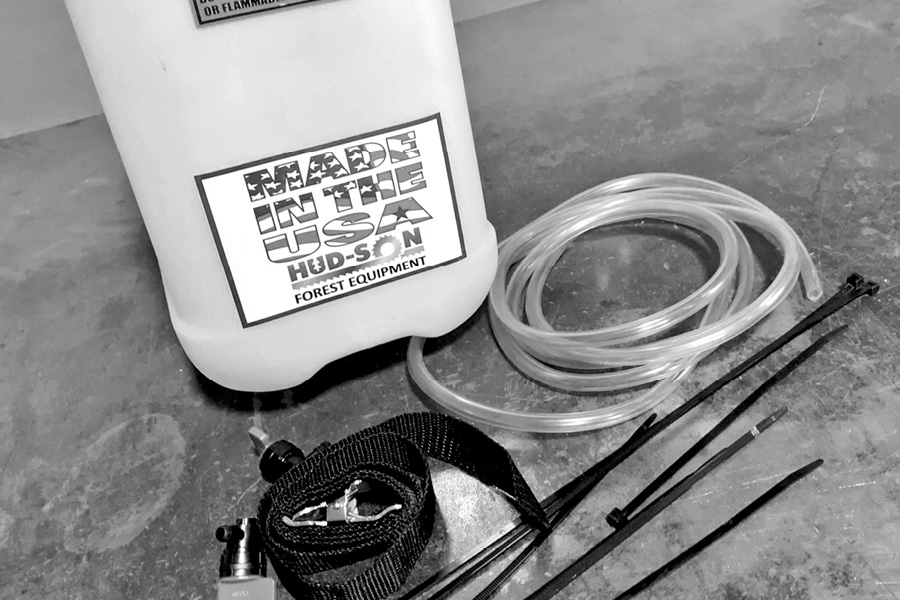
First connect one end of the tubing to the tank. Then cut the tubing about 6 inches from the tank and install a shutoff valve.
Then start securing your tubing to the frame with zip ties as shown.
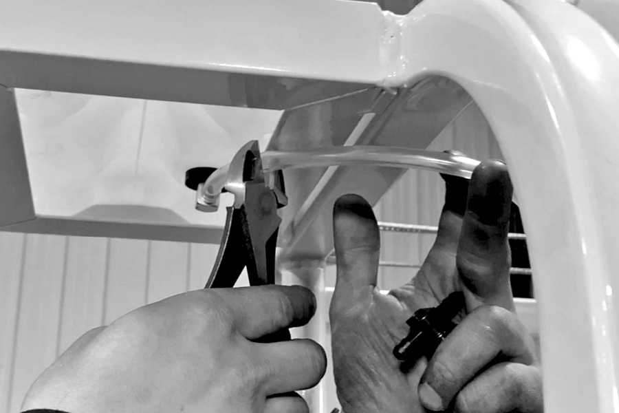
Be sure not to over tighten the zip ties. Continue to bring the tubing down the frame and then over to the head, feeding it underneath the clutch assembly and securing it with zip ties.
Bring it over to the side of the mill head and install the second shutoff valve, securing it with zip ties over the connections to the mill head.
Now slide the moveable guide all the way in and connect the lube line to the blade lube bracket on adjustable guide.
Then raise and lower your head and make sure there are no kinks that develop in your lube line from raising or lowering the head.
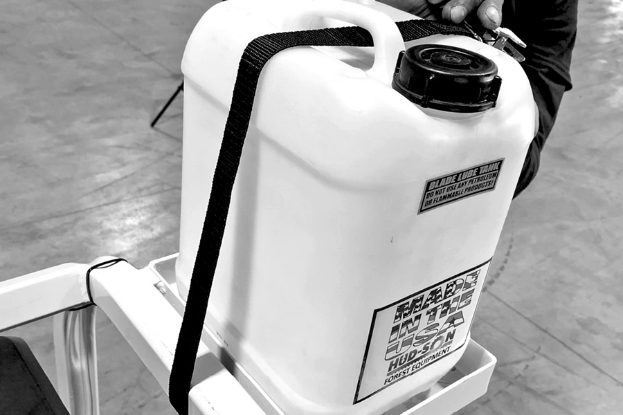
Secure the lube tank in the bracket with the provided strap.
Step 25 (Video – 32:06)
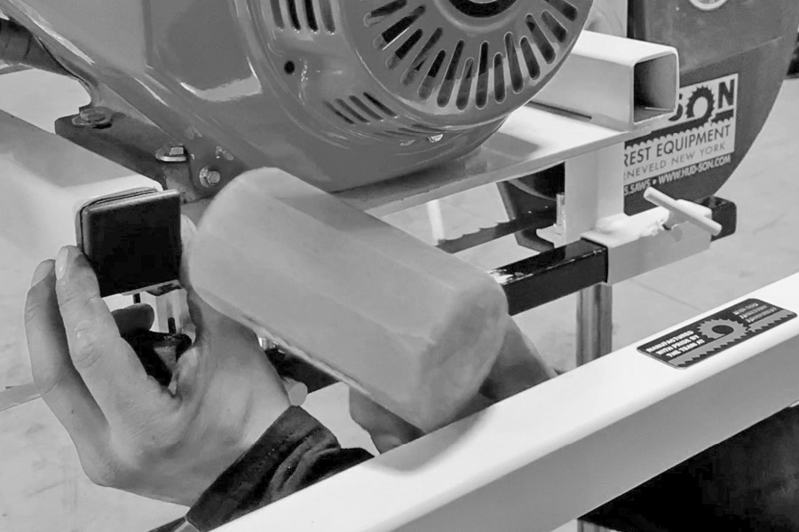
Install the plastic end caps
Locate the plastic end cap kit and, using a soft mallet, install the plastic caps as shown.
Make sure your blade tension is set, then start your sawmill and let it run for about 5 min.
Do a walk around while it is running and make sure you did not forget to tighten the bolts, nuts, or clamps.
Now your sawmill is fully assembled and adjusted. You are ready to start sawing and producing good quality lumber.
Always remember that when you are done sawing lumber with your mill, release the tension off the blade and make sure the head is set all the way down.
If you’re not going to use the sawmill for a while it is best to remove the blade, lightly oil it, and hang it inside, out of the weather.
Remember to read your operator’s manual before operating the sawmill. There is a lot of good, useful information in the manual about your sawmill.
Stay safe and happy sawing.